

5.2 Interphase Characterisation of PVA-Based Bionanocomposites
117
Interphase
Inner interface
PVA matrices
Outer interface
HNT
PVA matrices
Inner interface
Interphase
Outer interface
Outer interface
Inner interface
Effective interphase
Cloisite 30B
PVA matrices
Effective interphase
PVA matrices
Outer interface Inner interface
Cloisite 30B
(a)
(b)
(c)
(d)
(e)
(f)
HNT
HNT
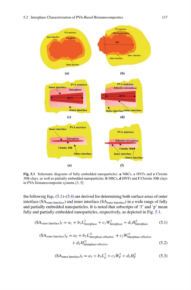
Fig. 5.1 Schematic diagrams of fully embedded nanoparticles: a NBCs, c HNTs and e Cloisite
30B clays, as well as partially embedded nanoparticles: b NBCs, d HNTs and f Cloisite 30B clays
in PVA bionanocomposite systems [3, 5]
the following Eqs. (5.1)–(5.4) are derived for determining both surface areas of outer
interface (SA outer Interface ) and inner interface (SA inner Interface ) in a wide range of fully
and partially embedded nanoparticles. It is noted that subscripts of ‘f’ and ‘p’ mean
fully and partially embedded nanoparticles, respectively, as depicted in Fig. 5.1.
(SA outer Interface ) f = a 1 + b 1 L
2
Interphase + c 1 W
2
Interphase + d 1 H
2
Interphase
(5.1)
(SA outer Interface ) p = a 2 + b 2 L
Interphase-effective + c 2 W
Interphase-effective
+ d 2 H
Interphase-effective
(5.2)
(SA inner Interface ) f = a 3 + b 3 L
2
p + c 3 W
2
P + d 3 H
2
P
(5.3)
117
Interphase
Inner interface
PVA matrices
Outer interface
HNT
PVA matrices
Inner interface
Interphase
Outer interface
Outer interface
Inner interface
Effective interphase
Cloisite 30B
PVA matrices
Effective interphase
PVA matrices
Outer interface Inner interface
Cloisite 30B
(a)
(b)
(c)
(d)
(e)
(f)
HNT
HNT
Fig. 5.1 Schematic diagrams of fully embedded nanoparticles: a NBCs, c HNTs and e Cloisite
30B clays, as well as partially embedded nanoparticles: b NBCs, d HNTs and f Cloisite 30B clays
in PVA bionanocomposite systems [3, 5]
the following Eqs. (5.1)–(5.4) are derived for determining both surface areas of outer
interface (SA outer Interface ) and inner interface (SA inner Interface ) in a wide range of fully
and partially embedded nanoparticles. It is noted that subscripts of ‘f’ and ‘p’ mean
fully and partially embedded nanoparticles, respectively, as depicted in Fig. 5.1.
(SA outer Interface ) f = a 1 + b 1 L
2
Interphase + c 1 W
2
Interphase + d 1 H
2
Interphase
(5.1)
(SA outer Interface ) p = a 2 + b 2 L
Interphase-effective + c 2 W
Interphase-effective
+ d 2 H
Interphase-effective
(5.2)
(SA inner Interface ) f = a 3 + b 3 L
2
p + c 3 W
2
P + d 3 H
2
P
(5.3)