

3 The Measurements of the Oxygen Reduction Reaction
35
potential and current density by controlling a given current density. The apparatus
used in this method is simple and easy to control, but is not suitable for electrodes
that vary greatly in current density or electrode surface state. The constant potential
method is a technique for controlling the potential of a given electrode and measuring
the relationship between the potential of the electrode and the current density. It is
also the most widely used method.
According to the relationship between electrode process and time, the test method
can be divided into steady-state method and transient method. The steady-state
method means the current potential curve of the measuring electrode in a steady
state, in this case, the current density and the electrode potential are independent of
time and do not change with time. The transient method is a curve showing the current
potential change of the electrode process when the steady state is not reached, and
the influence of the time factor on the electrode reaction is considered. The following
mainly introduces the basic working principle of the constant potential method for
measuring cyclic voltammetry.
The first use of cyclic voltammetry for scientific research dates back to about
80 years ago—Electrochemical studies by Heyrovsky et al. In their research, linear
scanning and cyclic voltammetry have been used for polarographic analysis. The
working electrode of this test is mercury, the counter electrode and the reference
electrode are both large-area calomel electrodes, and the potential region of interest
is negative compared with the calomel electrode, so the cyclic voltammetry curve
appears in the first quadrant. The study did not use the mathematical analysis of
reversible and irreversible reaction electron transfer proposed by Matsuda and Ayabe
in 1955 to determine the positive sweep potential. Moreover, there is no electronic
potentiostat (invented in 1954), and the calomel electrode serves as both the counter
electrode and the reference electrode, so it is necessary to correct the voltage drop
caused by the solution resistance between the working electrode and the calomel
electrode. After extensive application of potentiostats, cyclic voltammetry and linear
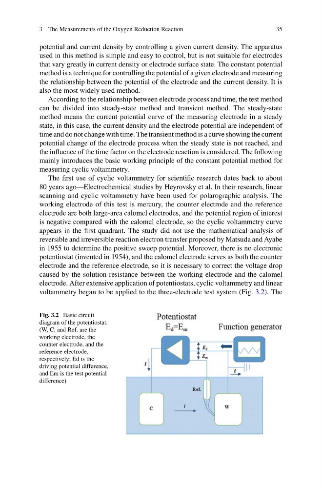
voltammetry began to be applied to the three-electrode test system (Fig. 3.2). The
Fig. 3.2 Basic circuit
diagram of the potentiostat.
(W, C, and Ref. are the
working electrode, the
counter electrode, and the
reference electrode,
respectively; Ed is the
driving potential difference,
and Em is the test potential
difference)
35
potential and current density by controlling a given current density. The apparatus
used in this method is simple and easy to control, but is not suitable for electrodes
that vary greatly in current density or electrode surface state. The constant potential
method is a technique for controlling the potential of a given electrode and measuring
the relationship between the potential of the electrode and the current density. It is
also the most widely used method.
According to the relationship between electrode process and time, the test method
can be divided into steady-state method and transient method. The steady-state
method means the current potential curve of the measuring electrode in a steady
state, in this case, the current density and the electrode potential are independent of
time and do not change with time. The transient method is a curve showing the current
potential change of the electrode process when the steady state is not reached, and
the influence of the time factor on the electrode reaction is considered. The following
mainly introduces the basic working principle of the constant potential method for
measuring cyclic voltammetry.
The first use of cyclic voltammetry for scientific research dates back to about
80 years ago—Electrochemical studies by Heyrovsky et al. In their research, linear
scanning and cyclic voltammetry have been used for polarographic analysis. The
working electrode of this test is mercury, the counter electrode and the reference
electrode are both large-area calomel electrodes, and the potential region of interest
is negative compared with the calomel electrode, so the cyclic voltammetry curve
appears in the first quadrant. The study did not use the mathematical analysis of
reversible and irreversible reaction electron transfer proposed by Matsuda and Ayabe
in 1955 to determine the positive sweep potential. Moreover, there is no electronic
potentiostat (invented in 1954), and the calomel electrode serves as both the counter
electrode and the reference electrode, so it is necessary to correct the voltage drop
caused by the solution resistance between the working electrode and the calomel
electrode. After extensive application of potentiostats, cyclic voltammetry and linear
voltammetry began to be applied to the three-electrode test system (Fig. 3.2). The
Fig. 3.2 Basic circuit
diagram of the potentiostat.
(W, C, and Ref. are the
working electrode, the
counter electrode, and the
reference electrode,
respectively; Ed is the
driving potential difference,
and Em is the test potential
difference)