

9 Mössbauer Spectroscopic Studies on Atomic Diffusion in Materials
465
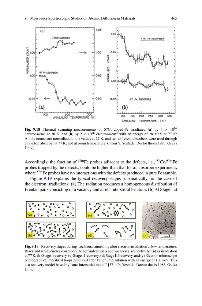
Fig. 9.18 Thermal scanning measurements of 57Co-doped-Fe irradiated (a) by 4 × 10 16
neutrons/cm 2 at 30 K, and (b) by 2 × 10 18 electrons/cm 2 with an energy of 28 MeV at 77 K:
All the counts are normalized to the values at 77 K, and two different absorbers were used through
an Fe foil absorber at 77 K, and at room temperature (From Y. Yoshida, Doctor thesis 1983, Osaka
Univ.)
Accordingly, the fraction of
57m Fe probes adjacent to the defects, i.e.,
57 Co/
57m Fe
probes trapped by the defects, could be higher than that for an absorber experiment,
where
57m Fe probes have no interactions with the defects produced in pure Fe sample.
Figure 9.19 explains the typical recovery stages schematically for the case of
the electron irradiations: (a) The radiation produces a homogeneous distribution of
Frenkel pairs consisting of a vacancy and a self-interstitial Fe atom. (b) At Stage I at
Fig. 9.19 Recovery stages during isochronal annealing after electron irradiation at low temperature.
Black and white circles correspond to self-interstitials and vacancies, respectively: (a) as irradiation
at 77 K, (b) Stage I recovery, (c) Stage II recovery, (d) Stage III recovery, and (e) Electron microscope
photograph of interstitial loops produced after Fe ion implantation with an energy of 100 keV. This
is a recovery model based by “one-interstitial model” [37]. (Y. Yoshida, Doctor thesis 1983, Osaka
Univ.)
465
Fig. 9.18 Thermal scanning measurements of 57Co-doped-Fe irradiated (a) by 4 × 10 16
neutrons/cm 2 at 30 K, and (b) by 2 × 10 18 electrons/cm 2 with an energy of 28 MeV at 77 K:
All the counts are normalized to the values at 77 K, and two different absorbers were used through
an Fe foil absorber at 77 K, and at room temperature (From Y. Yoshida, Doctor thesis 1983, Osaka
Univ.)
Accordingly, the fraction of
57m Fe probes adjacent to the defects, i.e.,
57 Co/
57m Fe
probes trapped by the defects, could be higher than that for an absorber experiment,
where
57m Fe probes have no interactions with the defects produced in pure Fe sample.
Figure 9.19 explains the typical recovery stages schematically for the case of
the electron irradiations: (a) The radiation produces a homogeneous distribution of
Frenkel pairs consisting of a vacancy and a self-interstitial Fe atom. (b) At Stage I at
Fig. 9.19 Recovery stages during isochronal annealing after electron irradiation at low temperature.
Black and white circles correspond to self-interstitials and vacancies, respectively: (a) as irradiation
at 77 K, (b) Stage I recovery, (c) Stage II recovery, (d) Stage III recovery, and (e) Electron microscope
photograph of interstitial loops produced after Fe ion implantation with an energy of 100 keV. This
is a recovery model based by “one-interstitial model” [37]. (Y. Yoshida, Doctor thesis 1983, Osaka
Univ.)