

384
M. Reissner
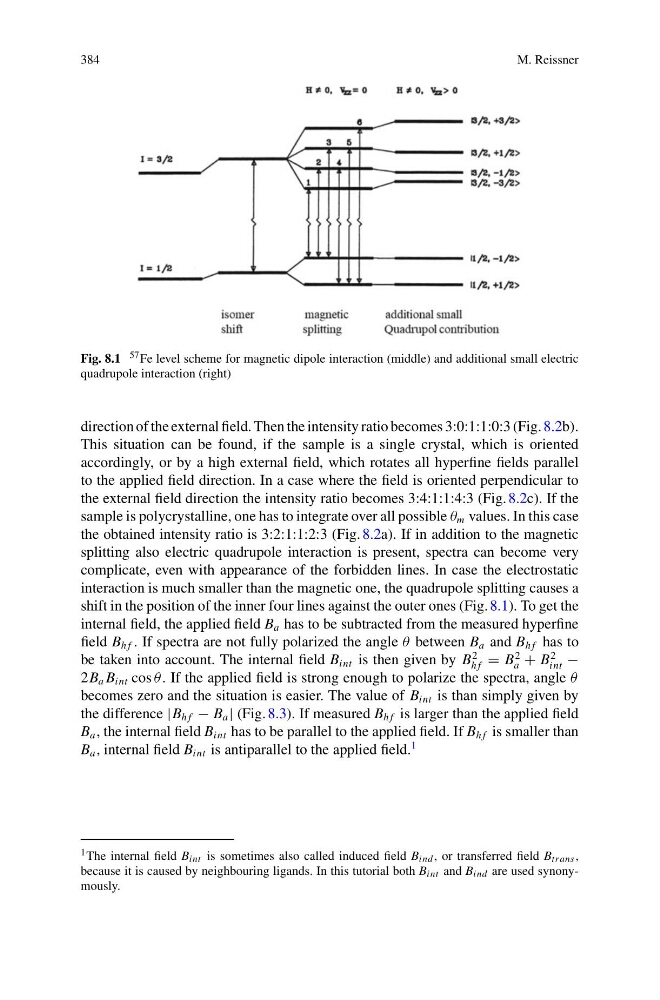
Fig. 8.1 57 Fe level scheme for magnetic dipole interaction (middle) and additional small electric
quadrupole interaction (right)
direction of the external field. Then the intensity ratio becomes 3:0:1:1:0:3 (Fig. 8.2b).
This situation can be found, if the sample is a single crystal, which is oriented
accordingly, or by a high external field, which rotates all hyperfine fields parallel
to the applied field direction. In a case where the field is oriented perpendicular to
the external field direction the intensity ratio becomes 3:4:1:1:4:3 (Fig. 8.2c). If the
sample is polycrystalline, one has to integrate over all possible θ m values. In this case
the obtained intensity ratio is 3:2:1:1:2:3 (Fig. 8.2a). If in addition to the magnetic
splitting also electric quadrupole interaction is present, spectra can become very
complicate, even with appearance of the forbidden lines. In case the electrostatic
interaction is much smaller than the magnetic one, the quadrupole splitting causes a
shift in the position of the inner four lines against the outer ones (Fig. 8.1). To get the
internal field, the applied field B a has to be subtracted from the measured hyperfine
field B h f . If spectra are not fully polarized the angle θ between B a and B h f has to
be taken into account. The internal field B int is then given by B
2
h f = B
2
a + B
2
int −
2B a B int cos θ . If the applied field is strong enough to polarize the spectra, angle θ
becomes zero and the situation is easier. The value of B int is than simply given by
the difference |B h f − B a | (Fig. 8.3). If measured B h f is larger than the applied field
B a , the internal field B int has to be parallel to the applied field. If B h f is smaller than
B a , internal field B int is antiparallel to the applied field.
1
1 The internal field B int is sometimes also called induced field B ind , or transferred field B trans ,
because it is caused by neighbouring ligands. In this tutorial both B int and B ind are used synonymously.
M. Reissner
Fig. 8.1 57 Fe level scheme for magnetic dipole interaction (middle) and additional small electric
quadrupole interaction (right)
direction of the external field. Then the intensity ratio becomes 3:0:1:1:0:3 (Fig. 8.2b).
This situation can be found, if the sample is a single crystal, which is oriented
accordingly, or by a high external field, which rotates all hyperfine fields parallel
to the applied field direction. In a case where the field is oriented perpendicular to
the external field direction the intensity ratio becomes 3:4:1:1:4:3 (Fig. 8.2c). If the
sample is polycrystalline, one has to integrate over all possible θ m values. In this case
the obtained intensity ratio is 3:2:1:1:2:3 (Fig. 8.2a). If in addition to the magnetic
splitting also electric quadrupole interaction is present, spectra can become very
complicate, even with appearance of the forbidden lines. In case the electrostatic
interaction is much smaller than the magnetic one, the quadrupole splitting causes a
shift in the position of the inner four lines against the outer ones (Fig. 8.1). To get the
internal field, the applied field B a has to be subtracted from the measured hyperfine
field B h f . If spectra are not fully polarized the angle θ between B a and B h f has to
be taken into account. The internal field B int is then given by B
2
h f = B
2
a + B
2
int −
2B a B int cos θ . If the applied field is strong enough to polarize the spectra, angle θ
becomes zero and the situation is easier. The value of B int is than simply given by
the difference |B h f − B a | (Fig. 8.3). If measured B h f is larger than the applied field
B a , the internal field B int has to be parallel to the applied field. If B h f is smaller than
B a , internal field B int is antiparallel to the applied field.
1
1 The internal field B int is sometimes also called induced field B ind , or transferred field B trans ,
because it is caused by neighbouring ligands. In this tutorial both B int and B ind are used synonymously.