

Preliminary Study on Integrated Simulation
293
Where T in is the temperature at the end of each pipe (The temperature of the entry
node); N in is the number of pipes connected to the inlet of node; T out is the temperature
at the start of each pipe (The temperature of the outflow node); N out is the number of
pipes connected to the outlet of node.
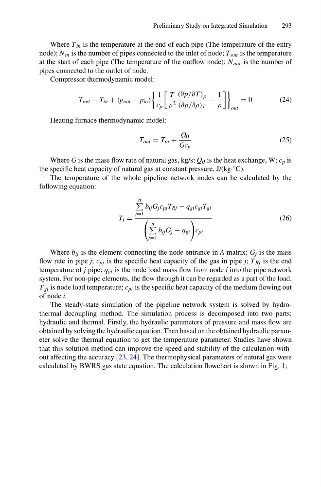
Compressor thermodynamic model:
T out − T in + (p out − p in )
1
c p
T
ρ 2
(∂p/∂T ) ρ
(∂p/∂ρ) T
−
1
ρ
out
= 0
( 2 4 )
Heating furnace thermodynamic model:
T out = T in +
Q 0
Gc p
(25)
Where G is the mass flow rate of natural gas, kg/s; Q 0 is the heat exchange, W; c p is
the specific heat capacity of natural gas at constant pressure, J/(kg·°C).
The temperature of the whole pipeline network nodes can be calculated by the
following equation:
T i =
n
j=1
b ij G j c pj T Rj − q gi c gi T gi
n
j=1
b ij G j − q gi
c pi
(26)
Where b ij is the element connecting the node entrance in A matrix; G j is the mass
flow rate in pipe j; c pj is the specific heat capacity of the gas in pipe j; T Rj is the end
temperature of j pipe; q gi is the node load mass flow from node i into the pipe network
system. For non-pipe elements, the flow through it can be regarded as a part of the load.
T gi is node load temperature; c pi is the specific heat capacity of the medium flowing out
of node i.
The steady-state simulation of the pipeline network system is solved by hydrothermal decoupling method. The simulation process is decomposed into two parts:
hydraulic and thermal. Firstly, the hydraulic parameters of pressure and mass flow are
obtained by solving the hydraulic equation. Then based on the obtained hydraulic parameter solve the thermal equation to get the temperature parameter. Studies have shown
that this solution method can improve the speed and stability of the calculation without affecting the accuracy [23, 24]. The thermophysical parameters of natural gas were
calculated by BWRS gas state equation. The calculation flowchart is shown in Fig. 1;
293
Where T in is the temperature at the end of each pipe (The temperature of the entry
node); N in is the number of pipes connected to the inlet of node; T out is the temperature
at the start of each pipe (The temperature of the outflow node); N out is the number of
pipes connected to the outlet of node.
Compressor thermodynamic model:
T out − T in + (p out − p in )
1
c p
T
ρ 2
(∂p/∂T ) ρ
(∂p/∂ρ) T
−
1
ρ
out
= 0
( 2 4 )
Heating furnace thermodynamic model:
T out = T in +
Q 0
Gc p
(25)
Where G is the mass flow rate of natural gas, kg/s; Q 0 is the heat exchange, W; c p is
the specific heat capacity of natural gas at constant pressure, J/(kg·°C).
The temperature of the whole pipeline network nodes can be calculated by the
following equation:
T i =
n
j=1
b ij G j c pj T Rj − q gi c gi T gi
n
j=1
b ij G j − q gi
c pi
(26)
Where b ij is the element connecting the node entrance in A matrix; G j is the mass
flow rate in pipe j; c pj is the specific heat capacity of the gas in pipe j; T Rj is the end
temperature of j pipe; q gi is the node load mass flow from node i into the pipe network
system. For non-pipe elements, the flow through it can be regarded as a part of the load.
T gi is node load temperature; c pi is the specific heat capacity of the medium flowing out
of node i.
The steady-state simulation of the pipeline network system is solved by hydrothermal decoupling method. The simulation process is decomposed into two parts:
hydraulic and thermal. Firstly, the hydraulic parameters of pressure and mass flow are
obtained by solving the hydraulic equation. Then based on the obtained hydraulic parameter solve the thermal equation to get the temperature parameter. Studies have shown
that this solution method can improve the speed and stability of the calculation without affecting the accuracy [23, 24]. The thermophysical parameters of natural gas were
calculated by BWRS gas state equation. The calculation flowchart is shown in Fig. 1;