

186
W. Li et al.
Where, P 1 -the hydrodynamic pressure at point 1, Pa; Z 1 -the elevation of point 1, m;
P 2 -the hydrodynamic pressure at point 2, Pa; Z 2 -the elevation of point 2, m; P f -the
friction losses from 1 to 2; Pa-additional pressure loss due to gas accumulation in
pipeline from 1 to 2.
By deforming formula (1), formula (2) is obtained.
P 2 = P 1 − ρg(Z 2 − Z 1 ) − P f − P a
(2)
In the commissioning of continuous undulating section, there are three flow forms
in the pipeline according to the different terrain.
(1) Air mass segment
Although many exhaust measures are taken during the commissioning, a certain
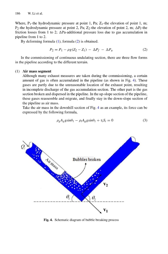
amount of gas is often accumulated in the pipeline (as shown in Fig. 4). These
gases are partly due to the unreasonable location of the exhaust point, resulting
in incomplete discharge of the gas accumulation section. The other part is the gas
section broken and dispersed in the pipeline. In the up-slope section of the pipeline,
these gases reassemble and migrate, and finally stay in the down-slope section of
the pipeline as air mass.
Take the air mass in the downhill section of Fig. 4 as an example, its force can be
expressed by the following formula,
ρ g A g gsinθ 1 − ρ l A g gsinθ 1 + τ i S i = 0
( 3 )
Fig. 4. Schematic diagram of bubble breaking process
W. Li et al.
Where, P 1 -the hydrodynamic pressure at point 1, Pa; Z 1 -the elevation of point 1, m;
P 2 -the hydrodynamic pressure at point 2, Pa; Z 2 -the elevation of point 2, m; P f -the
friction losses from 1 to 2; Pa-additional pressure loss due to gas accumulation in
pipeline from 1 to 2.
By deforming formula (1), formula (2) is obtained.
P 2 = P 1 − ρg(Z 2 − Z 1 ) − P f − P a
(2)
In the commissioning of continuous undulating section, there are three flow forms
in the pipeline according to the different terrain.
(1) Air mass segment
Although many exhaust measures are taken during the commissioning, a certain
amount of gas is often accumulated in the pipeline (as shown in Fig. 4). These
gases are partly due to the unreasonable location of the exhaust point, resulting
in incomplete discharge of the gas accumulation section. The other part is the gas
section broken and dispersed in the pipeline. In the up-slope section of the pipeline,
these gases reassemble and migrate, and finally stay in the down-slope section of
the pipeline as air mass.
Take the air mass in the downhill section of Fig. 4 as an example, its force can be
expressed by the following formula,
ρ g A g gsinθ 1 − ρ l A g gsinθ 1 + τ i S i = 0
( 3 )
Fig. 4. Schematic diagram of bubble breaking process