

142
R. Zhang et al.
of hydro-temperature-bubble under gas influx condition was established considering the
influence of bubble interaction on wellbore temperature when gas influx occurred.
Although there have been many mathematical models for calculating wellbore temperature, few scholars have studied transient wellbore temperature calculation model
by the coupled heat transfer and mass transfer as well as the coupled temperature and
pressure under the condition of multi-gradient controlled pressure drilling with HGS
injection. In this paper, the separation efficiency of HGS under different working conditions was investigated through experiments. Then, based on the influence of different
separation efficiency on mass transfer and heat transfer, the transient wellbore temperature calculation model of coupled heat and mass transfer as well as coupled temperature
and pressure was established. Then, under the assumption that the separation efficiency
is an invariant, the key factors affecting wellbore temperature and pressure are analyzed.
The influence of key factors on wellbore temperature and pressure during the circulation
process of multi-gradient pressure control drilling with HGS injection was studied comprehensively by combining experimental research with theoretical calculation model,
which provides better technical support for improving the precision of pressure control,
ensuring safe and efficient of drilling under the condition of narrow density window.
2 Separation Technology of HGS and Analysis of Key Factors
Influencing Separation Efficiency
2.1 Experimental Study on Separation Technology
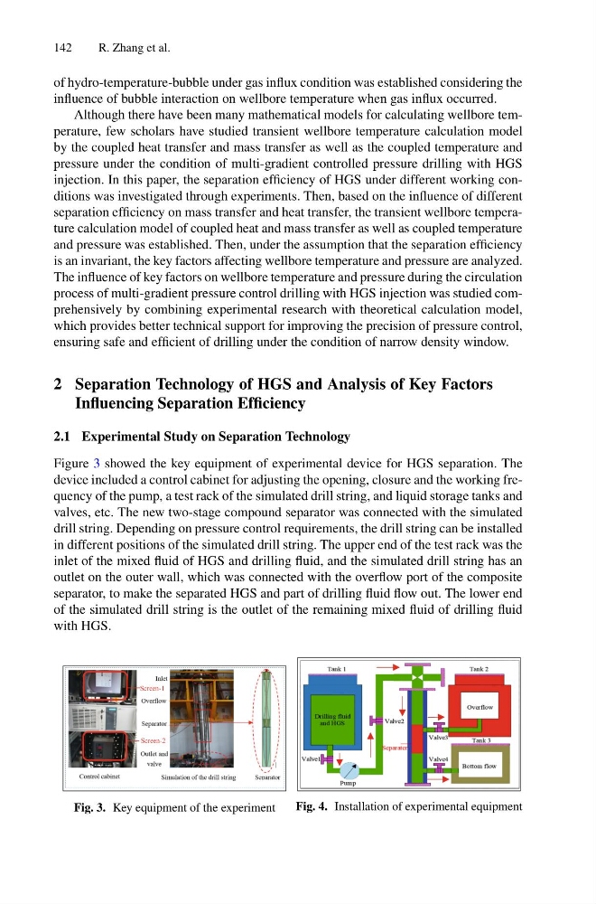
Figure 3 showed the key equipment of experimental device for HGS separation. The
device included a control cabinet for adjusting the opening, closure and the working frequency of the pump, a test rack of the simulated drill string, and liquid storage tanks and
valves, etc. The new two-stage compound separator was connected with the simulated
drill string. Depending on pressure control requirements, the drill string can be installed
in different positions of the simulated drill string. The upper end of the test rack was the
inlet of the mixed fluid of HGS and drilling fluid, and the simulated drill string has an
outlet on the outer wall, which was connected with the overflow port of the composite
separator, to make the separated HGS and part of drilling fluid flow out. The lower end
of the simulated drill string is the outlet of the remaining mixed fluid of drilling fluid
with HGS.
Screen-2
Screen-1
Fig. 3. Key equipment of the experiment
Fig. 4. Installation of experimental equipment
R. Zhang et al.
of hydro-temperature-bubble under gas influx condition was established considering the
influence of bubble interaction on wellbore temperature when gas influx occurred.
Although there have been many mathematical models for calculating wellbore temperature, few scholars have studied transient wellbore temperature calculation model
by the coupled heat transfer and mass transfer as well as the coupled temperature and
pressure under the condition of multi-gradient controlled pressure drilling with HGS
injection. In this paper, the separation efficiency of HGS under different working conditions was investigated through experiments. Then, based on the influence of different
separation efficiency on mass transfer and heat transfer, the transient wellbore temperature calculation model of coupled heat and mass transfer as well as coupled temperature
and pressure was established. Then, under the assumption that the separation efficiency
is an invariant, the key factors affecting wellbore temperature and pressure are analyzed.
The influence of key factors on wellbore temperature and pressure during the circulation
process of multi-gradient pressure control drilling with HGS injection was studied comprehensively by combining experimental research with theoretical calculation model,
which provides better technical support for improving the precision of pressure control,
ensuring safe and efficient of drilling under the condition of narrow density window.
2 Separation Technology of HGS and Analysis of Key Factors
Influencing Separation Efficiency
2.1 Experimental Study on Separation Technology
Figure 3 showed the key equipment of experimental device for HGS separation. The
device included a control cabinet for adjusting the opening, closure and the working frequency of the pump, a test rack of the simulated drill string, and liquid storage tanks and
valves, etc. The new two-stage compound separator was connected with the simulated
drill string. Depending on pressure control requirements, the drill string can be installed
in different positions of the simulated drill string. The upper end of the test rack was the
inlet of the mixed fluid of HGS and drilling fluid, and the simulated drill string has an
outlet on the outer wall, which was connected with the overflow port of the composite
separator, to make the separated HGS and part of drilling fluid flow out. The lower end
of the simulated drill string is the outlet of the remaining mixed fluid of drilling fluid
with HGS.
Screen-2
Screen-1
Fig. 3. Key equipment of the experiment
Fig. 4. Installation of experimental equipment