

A New Locking-Free Thick/Thin Shell Element
111
4.3 Hemispherical Shell with a Top Hole
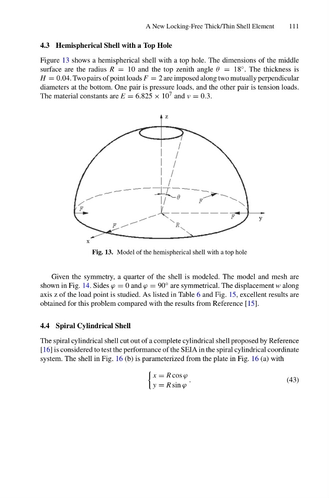
Figure 13 shows a hemispherical shell with a top hole. The dimensions of the middle
surface are the radius R = 10 and the top zenith angle θ = 18 ◦ . The thickness is
H = 0.04. Two pairs of point loads F = 2 are imposed along two mutually perpendicular
diameters at the bottom. One pair is pressure loads, and the other pair is tension loads.
The material constants are E = 6.825 × 10 7 and ν = 0.3.
Fig. 13. Model of the hemispherical shell with a top hole
Given the symmetry, a quarter of the shell is modeled. The model and mesh are
shown in Fig. 14. Sides ϕ = 0 and ϕ = 90 ◦ are symmetrical. The displacement w along
axis z of the load point is studied. As listed in Table 6 and Fig. 15, excellent results are
obtained for this problem compared with the results from Reference [15].
4.4 Spiral Cylindrical Shell
The spiral cylindrical shell cut out of a complete cylindrical shell proposed by Reference
[16] is considered to test the performance of the SEIA in the spiral cylindrical coordinate
system. The shell in Fig. 16 (b) is parameterized from the plate in Fig. 16 (a) with
x = R cos ϕ
y = R sin ϕ
.
(43)
111
4.3 Hemispherical Shell with a Top Hole
Figure 13 shows a hemispherical shell with a top hole. The dimensions of the middle
surface are the radius R = 10 and the top zenith angle θ = 18 ◦ . The thickness is
H = 0.04. Two pairs of point loads F = 2 are imposed along two mutually perpendicular
diameters at the bottom. One pair is pressure loads, and the other pair is tension loads.
The material constants are E = 6.825 × 10 7 and ν = 0.3.
Fig. 13. Model of the hemispherical shell with a top hole
Given the symmetry, a quarter of the shell is modeled. The model and mesh are
shown in Fig. 14. Sides ϕ = 0 and ϕ = 90 ◦ are symmetrical. The displacement w along
axis z of the load point is studied. As listed in Table 6 and Fig. 15, excellent results are
obtained for this problem compared with the results from Reference [15].
4.4 Spiral Cylindrical Shell
The spiral cylindrical shell cut out of a complete cylindrical shell proposed by Reference
[16] is considered to test the performance of the SEIA in the spiral cylindrical coordinate
system. The shell in Fig. 16 (b) is parameterized from the plate in Fig. 16 (a) with
x = R cos ϕ
y = R sin ϕ
.
(43)