

A New Locking-Free Thick/Thin Shell Element
109
Table 3. ˜
w with different H /L for the square plate
1 × 10 −4 1 × 10 −3 1 × 10 −2 0.1
0.15
0.2
0.25
0.3
4 × 4
0.1194
0.1217
0.1266
0.1506 0.1789 0.2173 0.2659 0.3247
8 × 8
0.1256
0.1264
0.1269
0.1506 0.1789 0.2173 0.2659 0.3247
16 × 16
0.1264
0.1266
0.1269
0.1505 0.1789 0.2173 0.2659 0.3247
Figure 13 0.1266
0.1266
0.1269
0.1506 0.1789 0.2173 0.2659 0.3247
Exact
0.1265
0.1265
0.1265
0.1499 0.1798 0.2167 0.2675 0.3227
4.2 Circumferentially Closed Cylindrical Shell
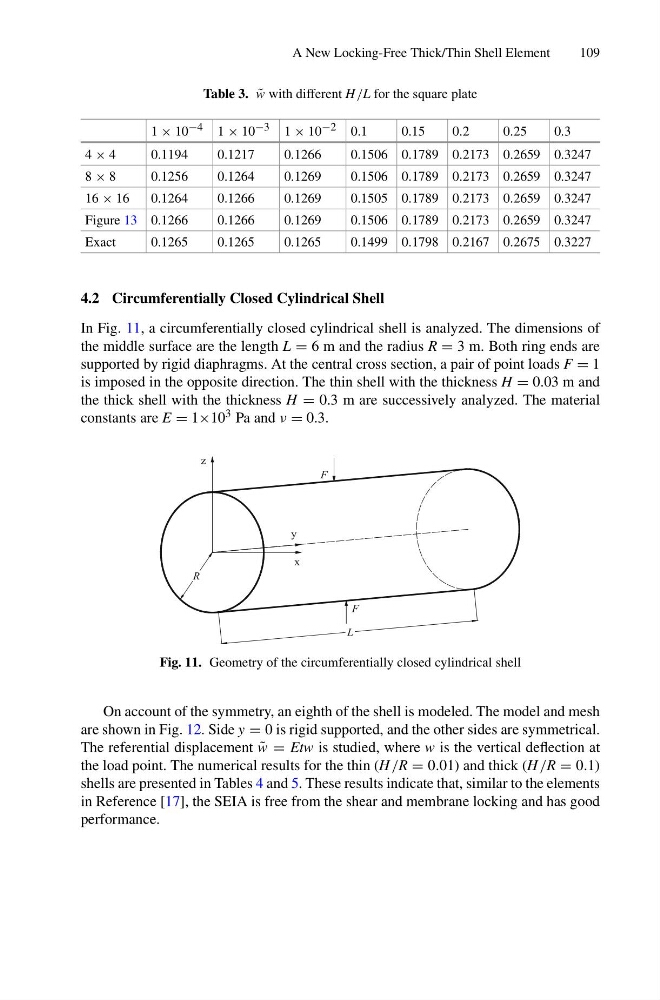
In Fig. 11, a circumferentially closed cylindrical shell is analyzed. The dimensions of
the middle surface are the length L = 6 m and the radius R = 3 m. Both ring ends are
supported by rigid diaphragms. At the central cross section, a pair of point loads F = 1
is imposed in the opposite direction. The thin shell with the thickness H = 0.03 m and
the thick shell with the thickness H = 0.3 m are successively analyzed. The material
constants are E = 1×10 3 Pa and ν = 0.3.
L
F
F
x
y
z
R
Fig. 11. Geometry of the circumferentially closed cylindrical shell
On account of the symmetry, an eighth of the shell is modeled. The model and mesh
are shown in Fig. 12. Side y = 0 is rigid supported, and the other sides are symmetrical.
The referential displacement ˜
w = Etw is studied, where w is the vertical deflection at
the load point. The numerical results for the thin (H /R = 0.01) and thick (H /R = 0.1)
shells are presented in Tables 4 and 5. These results indicate that, similar to the elements
in Reference [17], the SEIA is free from the shear and membrane locking and has good
performance.
109
Table 3. ˜
w with different H /L for the square plate
1 × 10 −4 1 × 10 −3 1 × 10 −2 0.1
0.15
0.2
0.25
0.3
4 × 4
0.1194
0.1217
0.1266
0.1506 0.1789 0.2173 0.2659 0.3247
8 × 8
0.1256
0.1264
0.1269
0.1506 0.1789 0.2173 0.2659 0.3247
16 × 16
0.1264
0.1266
0.1269
0.1505 0.1789 0.2173 0.2659 0.3247
Figure 13 0.1266
0.1266
0.1269
0.1506 0.1789 0.2173 0.2659 0.3247
Exact
0.1265
0.1265
0.1265
0.1499 0.1798 0.2167 0.2675 0.3227
4.2 Circumferentially Closed Cylindrical Shell
In Fig. 11, a circumferentially closed cylindrical shell is analyzed. The dimensions of
the middle surface are the length L = 6 m and the radius R = 3 m. Both ring ends are
supported by rigid diaphragms. At the central cross section, a pair of point loads F = 1
is imposed in the opposite direction. The thin shell with the thickness H = 0.03 m and
the thick shell with the thickness H = 0.3 m are successively analyzed. The material
constants are E = 1×10 3 Pa and ν = 0.3.
L
F
F
x
y
z
R
Fig. 11. Geometry of the circumferentially closed cylindrical shell
On account of the symmetry, an eighth of the shell is modeled. The model and mesh
are shown in Fig. 12. Side y = 0 is rigid supported, and the other sides are symmetrical.
The referential displacement ˜
w = Etw is studied, where w is the vertical deflection at
the load point. The numerical results for the thin (H /R = 0.01) and thick (H /R = 0.1)
shells are presented in Tables 4 and 5. These results indicate that, similar to the elements
in Reference [17], the SEIA is free from the shear and membrane locking and has good
performance.