

A New Locking-Free Thick/Thin Shell Element
107
L
z
y
x
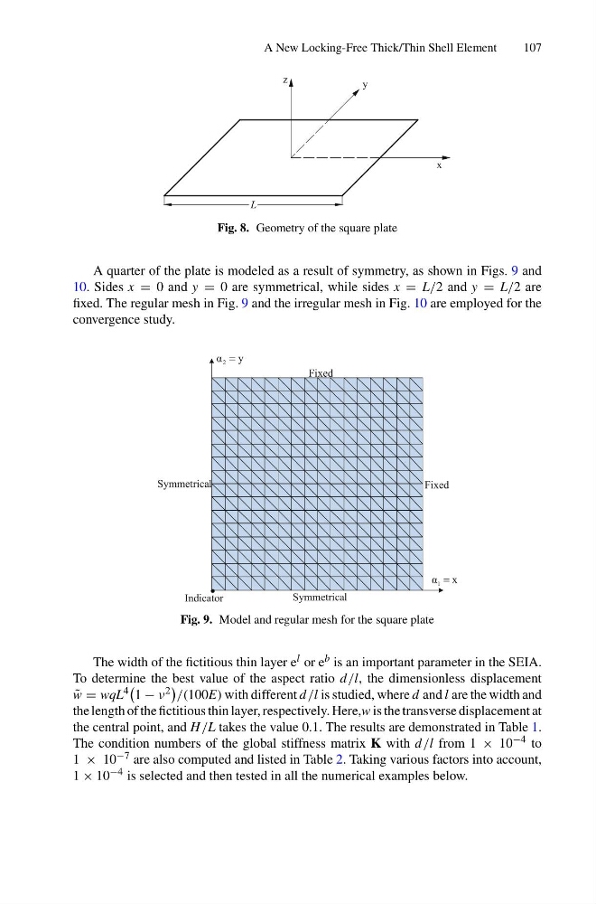
Fig. 8. Geometry of the square plate
A quarter of the plate is modeled as a result of symmetry, as shown in Figs. 9 and
10. Sides x = 0 and y = 0 are symmetrical, while sides x = L/2 and y = L/2 are
fixed. The regular mesh in Fig. 9 and the irregular mesh in Fig. 10 are employed for the
convergence study.
l
Symmetrica
l
Symmetrica
Indicator
Fixed
Fixed
y
α 2 =
x
α 1 =
Fig. 9. Model and regular mesh for the square plate
The width of the fictitious thin layer e l or e b is an important parameter in the SEIA.
To determine the best value of the aspect ratio d /l, the dimensionless displacement
˜
w = wqL 4
1 − ν 2
/(100E) with different d /l is studied, where d and l are the width and
the length of the fictitious thin layer, respectively. Here,w is the transverse displacement at
the central point, and H /L takes the value 0.1. The results are demonstrated in Table 1.
The condition numbers of the global stiffness matrix K with d /l from 1 × 10 −4 to
1 × 10 −7 are also computed and listed in Table 2. Taking various factors into account,
1 × 10 −4 is selected and then tested in all the numerical examples below.
107
L
z
y
x
Fig. 8. Geometry of the square plate
A quarter of the plate is modeled as a result of symmetry, as shown in Figs. 9 and
10. Sides x = 0 and y = 0 are symmetrical, while sides x = L/2 and y = L/2 are
fixed. The regular mesh in Fig. 9 and the irregular mesh in Fig. 10 are employed for the
convergence study.
l
Symmetrica
l
Symmetrica
Indicator
Fixed
Fixed
y
α 2 =
x
α 1 =
Fig. 9. Model and regular mesh for the square plate
The width of the fictitious thin layer e l or e b is an important parameter in the SEIA.
To determine the best value of the aspect ratio d /l, the dimensionless displacement
˜
w = wqL 4
1 − ν 2
/(100E) with different d /l is studied, where d and l are the width and
the length of the fictitious thin layer, respectively. Here,w is the transverse displacement at
the central point, and H /L takes the value 0.1. The results are demonstrated in Table 1.
The condition numbers of the global stiffness matrix K with d /l from 1 × 10 −4 to
1 × 10 −7 are also computed and listed in Table 2. Taking various factors into account,
1 × 10 −4 is selected and then tested in all the numerical examples below.