

74
C. Neugebauer et al.
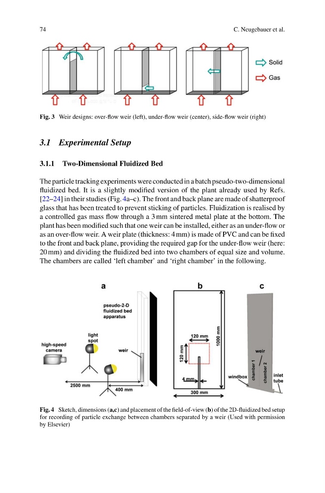
Fig. 3 Weir designs: over-flow weir (left), under-flow weir (center), side-flow weir (right)
3.1 Experimental Setup
3.1.1 Two-Dimensional Fluidized Bed
The particle tracking experiments were conducted in a batch pseudo-two-dimensional
fluidized bed. It is a slightly modified version of the plant already used by Refs.
[22–24] in their studies (Fig. 4a–c). The front and back plane are made of shatterproof
glass that has been treated to prevent sticking of particles. Fluidization is realised by
a controlled gas mass flow through a 3 mm sintered metal plate at the bottom. The
plant has been modified such that one weir can be installed, either as an under-flow or
as an over-flow weir. A weir plate (thickness: 4 mm) is made of PVC and can be fixed
to the front and back plane, providing the required gap for the under-flow weir (here:
20 mm) and dividing the fluidized bed into two chambers of equal size and volume.
The chambers are called ‘left chamber’ and ‘right chamber’ in the following.
Fig. 4 Sketch, dimensions (a,c) and placement of the field-of-view (b) of the 2D-fluidized bed setup
for recording of particle exchange between chambers separated by a weir (Used with permission
by Elsevier)
C. Neugebauer et al.
Fig. 3 Weir designs: over-flow weir (left), under-flow weir (center), side-flow weir (right)
3.1 Experimental Setup
3.1.1 Two-Dimensional Fluidized Bed
The particle tracking experiments were conducted in a batch pseudo-two-dimensional
fluidized bed. It is a slightly modified version of the plant already used by Refs.
[22–24] in their studies (Fig. 4a–c). The front and back plane are made of shatterproof
glass that has been treated to prevent sticking of particles. Fluidization is realised by
a controlled gas mass flow through a 3 mm sintered metal plate at the bottom. The
plant has been modified such that one weir can be installed, either as an under-flow or
as an over-flow weir. A weir plate (thickness: 4 mm) is made of PVC and can be fixed
to the front and back plane, providing the required gap for the under-flow weir (here:
20 mm) and dividing the fluidized bed into two chambers of equal size and volume.
The chambers are called ‘left chamber’ and ‘right chamber’ in the following.
Fig. 4 Sketch, dimensions (a,c) and placement of the field-of-view (b) of the 2D-fluidized bed setup
for recording of particle exchange between chambers separated by a weir (Used with permission
by Elsevier)