

490
R. Ahrens et al.
There are two topics that will be discussed in this section. From the modeling point
of view, a model for the sedimentation velocity u sed is needed. From the algorithmic
point of view, one has to detect whether the crystal left its mesh cell after the transport
step or even would hit the boundary of the domain if the transport step is performed
and appropriate numerical procedures have to be performed in these situations.
For the considered application, a crystallization process in a fluidized bed crystallizer, the sedimentation of crystals has to be taken into account. Sedimentation
depends on various aspects, like the form of the crystals and the actual local velocity
field. In our application, the crystals can attain quite different forms. Since we could
not find an appropriate sedimentation model in the literature, we decided to use as
basis a sedimentation model for spherical particles, see [7, pp. 58] for its derivation.
However, numerical studies in [6] showed that we had to modify this model for
our purposes. Concretely, a scaling factor was introduced. Finally, the sedimentation
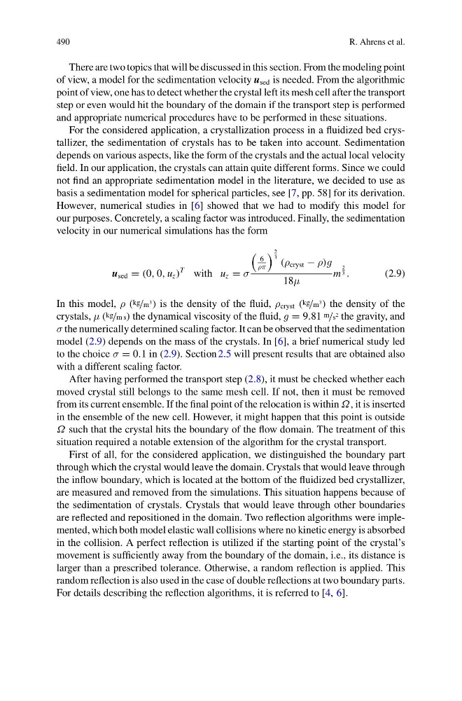
velocity in our numerical simulations has the form
u sed = (0, 0, u z )
T with u z = σ
6
ρπ
2
3 (ρ cryst − ρ)g
18μ
m
2
3 .
(2.9)
In this model, ρ ( kg /m
3
) is the density of the fluid, ρ cryst ( kg /m
3
) the density of the
crystals, μ ( kg /m s) the dynamical viscosity of the fluid, g = 9.81 m /s
2 the gravity, and
σ the numerically determined scaling factor. It can be observed that the sedimentation
model (2.9) depends on the mass of the crystals. In [6], a brief numerical study led
to the choice σ = 0.1 in (2.9). Section 2.5 will present results that are obtained also
with a different scaling factor.
After having performed the transport step (2.8), it must be checked whether each
moved crystal still belongs to the same mesh cell. If not, then it must be removed
from its current ensemble. If the final point of the relocation is within Ω, it is inserted
in the ensemble of the new cell. However, it might happen that this point is outside
Ω such that the crystal hits the boundary of the flow domain. The treatment of this
situation required a notable extension of the algorithm for the crystal transport.
First of all, for the considered application, we distinguished the boundary part
through which the crystal would leave the domain. Crystals that would leave through
the inflow boundary, which is located at the bottom of the fluidized bed crystallizer,
are measured and removed from the simulations. This situation happens because of
the sedimentation of crystals. Crystals that would leave through other boundaries
are reflected and repositioned in the domain. Two reflection algorithms were implemented, which both model elastic wall collisions where no kinetic energy is absorbed
in the collision. A perfect reflection is utilized if the starting point of the crystal’s
movement is sufficiently away from the boundary of the domain, i.e., its distance is
larger than a prescribed tolerance. Otherwise, a random reflection is applied. This
random reflection is also used in the case of double reflections at two boundary parts.
For details describing the reflection algorithms, it is referred to [4, 6].
R. Ahrens et al.
There are two topics that will be discussed in this section. From the modeling point
of view, a model for the sedimentation velocity u sed is needed. From the algorithmic
point of view, one has to detect whether the crystal left its mesh cell after the transport
step or even would hit the boundary of the domain if the transport step is performed
and appropriate numerical procedures have to be performed in these situations.
For the considered application, a crystallization process in a fluidized bed crystallizer, the sedimentation of crystals has to be taken into account. Sedimentation
depends on various aspects, like the form of the crystals and the actual local velocity
field. In our application, the crystals can attain quite different forms. Since we could
not find an appropriate sedimentation model in the literature, we decided to use as
basis a sedimentation model for spherical particles, see [7, pp. 58] for its derivation.
However, numerical studies in [6] showed that we had to modify this model for
our purposes. Concretely, a scaling factor was introduced. Finally, the sedimentation
velocity in our numerical simulations has the form
u sed = (0, 0, u z )
T with u z = σ
6
ρπ
2
3 (ρ cryst − ρ)g
18μ
m
2
3 .
(2.9)
In this model, ρ ( kg /m
3
) is the density of the fluid, ρ cryst ( kg /m
3
) the density of the
crystals, μ ( kg /m s) the dynamical viscosity of the fluid, g = 9.81 m /s
2 the gravity, and
σ the numerically determined scaling factor. It can be observed that the sedimentation
model (2.9) depends on the mass of the crystals. In [6], a brief numerical study led
to the choice σ = 0.1 in (2.9). Section 2.5 will present results that are obtained also
with a different scaling factor.
After having performed the transport step (2.8), it must be checked whether each
moved crystal still belongs to the same mesh cell. If not, then it must be removed
from its current ensemble. If the final point of the relocation is within Ω, it is inserted
in the ensemble of the new cell. However, it might happen that this point is outside
Ω such that the crystal hits the boundary of the flow domain. The treatment of this
situation required a notable extension of the algorithm for the crystal transport.
First of all, for the considered application, we distinguished the boundary part
through which the crystal would leave the domain. Crystals that would leave through
the inflow boundary, which is located at the bottom of the fluidized bed crystallizer,
are measured and removed from the simulations. This situation happens because of
the sedimentation of crystals. Crystals that would leave through other boundaries
are reflected and repositioned in the domain. Two reflection algorithms were implemented, which both model elastic wall collisions where no kinetic energy is absorbed
in the collision. A perfect reflection is utilized if the starting point of the crystal’s
movement is sufficiently away from the boundary of the domain, i.e., its distance is
larger than a prescribed tolerance. Otherwise, a random reflection is applied. This
random reflection is also used in the case of double reflections at two boundary parts.
For details describing the reflection algorithms, it is referred to [4, 6].