

416
K. Vaupel et al.
Fig. 1 Schematics of the
electrostatic precipitator,
with three wire electrodes
and copperplate anode
The schematics of the electrostatic precipitator are shown in Fig. 1. Dimensions
of the precipitation chamber are length L = 1.2 m, width W = 0.5 m and height H
= 0.3 m.
Particulate test material was dispersed by a K-Tron screw feeder combined with
an air pressure nozzle and homogenized before entering the precipitation chamber.
Inside the chamber three high voltage precipitation wire electrodes are placed along
the center axis, at a distance to the chamber inlet. The distance between the equally
spaced wires was 0.3 m. By using a high voltage supply (70 kV) corona discharge
was created. These charges precipitate particles from the aerosol on the conducting
copperplate. For optical analysis of the deposited particles, three stubs with a diameter
of 20 mm were mounted into the conducting copperplate. They were positioned
lengthwise with respect to the second electrode at a height of 0.15 m. Precipitated
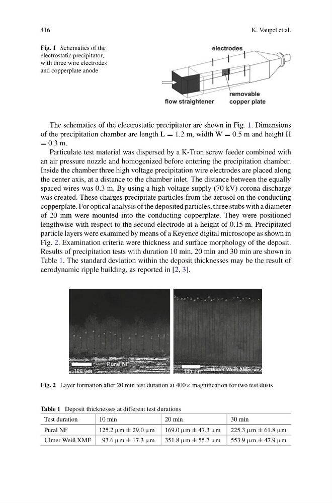
particle layers were examined by means of a Keyence digital microscope as shown in
Fig. 2. Examination criteria were thickness and surface morphology of the deposit.
Results of precipitation tests with duration 10 min, 20 min and 30 min are shown in
Table 1. The standard deviation within the deposit thicknesses may be the result of
aerodynamic ripple building, as reported in [2, 3].
Fig. 2 Layer formation after 20 min test duration at 400× magnification for two test dusts
Table 1 Deposit thicknesses at different test durations
Test duration
10 min
20 min
30 min
Pural NF
125.2 µm ± 29.0 µm
169.0 µm ± 47.3 µm
225.3 µm ± 61.8 µm
Ulmer Weiß XMF
93.6 µm ± 17.3 µm
351.8 µm ± 55.7 µm
553.9 µm ± 47.9 µm
K. Vaupel et al.
Fig. 1 Schematics of the
electrostatic precipitator,
with three wire electrodes
and copperplate anode
The schematics of the electrostatic precipitator are shown in Fig. 1. Dimensions
of the precipitation chamber are length L = 1.2 m, width W = 0.5 m and height H
= 0.3 m.
Particulate test material was dispersed by a K-Tron screw feeder combined with
an air pressure nozzle and homogenized before entering the precipitation chamber.
Inside the chamber three high voltage precipitation wire electrodes are placed along
the center axis, at a distance to the chamber inlet. The distance between the equally
spaced wires was 0.3 m. By using a high voltage supply (70 kV) corona discharge
was created. These charges precipitate particles from the aerosol on the conducting
copperplate. For optical analysis of the deposited particles, three stubs with a diameter
of 20 mm were mounted into the conducting copperplate. They were positioned
lengthwise with respect to the second electrode at a height of 0.15 m. Precipitated
particle layers were examined by means of a Keyence digital microscope as shown in
Fig. 2. Examination criteria were thickness and surface morphology of the deposit.
Results of precipitation tests with duration 10 min, 20 min and 30 min are shown in
Table 1. The standard deviation within the deposit thicknesses may be the result of
aerodynamic ripple building, as reported in [2, 3].
Fig. 2 Layer formation after 20 min test duration at 400× magnification for two test dusts
Table 1 Deposit thicknesses at different test durations
Test duration
10 min
20 min
30 min
Pural NF
125.2 µm ± 29.0 µm
169.0 µm ± 47.3 µm
225.3 µm ± 61.8 µm
Ulmer Weiß XMF
93.6 µm ± 17.3 µm
351.8 µm ± 55.7 µm
553.9 µm ± 47.9 µm