

8
S. Sander et al.
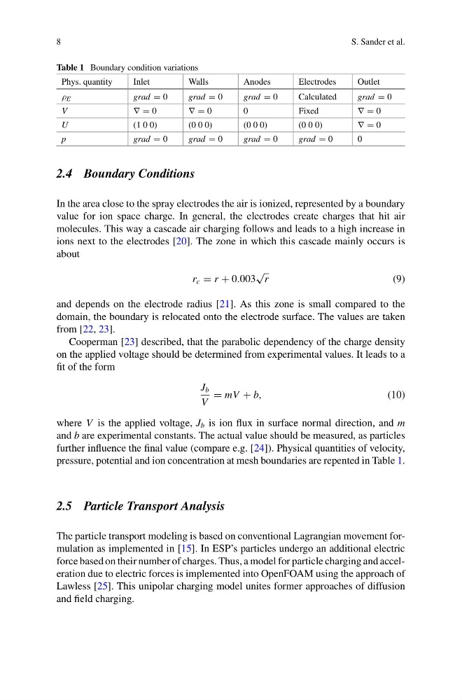
Table 1 Boundary condition variations
Phys. quantity
Inlet
Walls
Anodes
Electrodes
Outlet
ρ E
grad = 0
grad = 0
grad = 0
Calculated
grad = 0
V
∇ = 0
∇ = 0
0
Fixed
∇ = 0
U
(1 0 0)
(0 0 0)
(0 0 0)
(0 0 0)
∇ = 0
p
grad = 0
grad = 0
grad = 0
grad = 0
0
2.4 Boundary Conditions
In the area close to the spray electrodes the air is ionized, represented by a boundary
value for ion space charge. In general, the electrodes create charges that hit air
molecules. This way a cascade air charging follows and leads to a high increase in
ions next to the electrodes [20]. The zone in which this cascade mainly occurs is
about
r c = r + 0.003
√
r
(9)
and depends on the electrode radius [21]. As this zone is small compared to the
domain, the boundary is relocated onto the electrode surface. The values are taken
from [22, 23].
Cooperman [23] described, that the parabolic dependency of the charge density
on the applied voltage should be determined from experimental values. It leads to a
fit of the form
J b
V
= mV + b,
(10)
where V is the applied voltage, J b is ion flux in surface normal direction, and m
and b are experimental constants. The actual value should be measured, as particles
further influence the final value (compare e.g. [24]). Physical quantities of velocity,
pressure, potential and ion concentration at mesh boundaries are repented in Table 1.
2.5 Particle Transport Analysis
The particle transport modeling is based on conventional Lagrangian movement formulation as implemented in [15]. In ESP’s particles undergo an additional electric
force based on their number of charges. Thus, a model for particle charging and acceleration due to electric forces is implemented into OpenFOAM using the approach of
Lawless [25]. This unipolar charging model unites former approaches of diffusion
and field charging.
S. Sander et al.
Table 1 Boundary condition variations
Phys. quantity
Inlet
Walls
Anodes
Electrodes
Outlet
ρ E
grad = 0
grad = 0
grad = 0
Calculated
grad = 0
V
∇ = 0
∇ = 0
0
Fixed
∇ = 0
U
(1 0 0)
(0 0 0)
(0 0 0)
(0 0 0)
∇ = 0
p
grad = 0
grad = 0
grad = 0
grad = 0
0
2.4 Boundary Conditions
In the area close to the spray electrodes the air is ionized, represented by a boundary
value for ion space charge. In general, the electrodes create charges that hit air
molecules. This way a cascade air charging follows and leads to a high increase in
ions next to the electrodes [20]. The zone in which this cascade mainly occurs is
about
r c = r + 0.003
√
r
(9)
and depends on the electrode radius [21]. As this zone is small compared to the
domain, the boundary is relocated onto the electrode surface. The values are taken
from [22, 23].
Cooperman [23] described, that the parabolic dependency of the charge density
on the applied voltage should be determined from experimental values. It leads to a
fit of the form
J b
V
= mV + b,
(10)
where V is the applied voltage, J b is ion flux in surface normal direction, and m
and b are experimental constants. The actual value should be measured, as particles
further influence the final value (compare e.g. [24]). Physical quantities of velocity,
pressure, potential and ion concentration at mesh boundaries are repented in Table 1.
2.5 Particle Transport Analysis
The particle transport modeling is based on conventional Lagrangian movement formulation as implemented in [15]. In ESP’s particles undergo an additional electric
force based on their number of charges. Thus, a model for particle charging and acceleration due to electric forces is implemented into OpenFOAM using the approach of
Lawless [25]. This unipolar charging model unites former approaches of diffusion
and field charging.