

6.11 Myklestad Method
215
that end is considered as zero there. We calculate progressively from that end, till we
reach the other end, which is a simple support. Let the deflection and the bending
moment at the simply supported end be A l and A 2 . Next, we assume a shear force V
(say equal to 1.0) and zero slope at the left hand end and compute the deflection and
the bending moment at the other end. Let A 3 and A 4 be the values of the deflection
and the bending moment at the right hand end. If θ b0 and V 0 are the actual values of
the slope and the shear force at the left hand end, then the deflection and the bending
moment at the right hand end are
y e = A 1
θ b0
θ
b
+ A 3
V 0
V
M e = A 2
θ b0
θ
b
+ A 4
V 0
V
⎫
⎪ ⎬
⎪ ⎭
(6.88)
Equation (6.88) when written in matrix form becomes
y e
M e
=
A 1
θ
b
A 3
V
A 2
θ
b
A 4
V
θ b0
V 0
(6.89a)
If the value p
coincides with one of the natural frequencies, then the determinant
formed by the coefficients is equal to zero, that is
=
A 1
θ
b
A 3
V
A 2
θ
b
A 4
V
= 0
(6.89b)
The method comes under determinant search technique. A plot is made of
versus p
2 . The values of p
2 for which are zero are the natural frequencies
of the system.
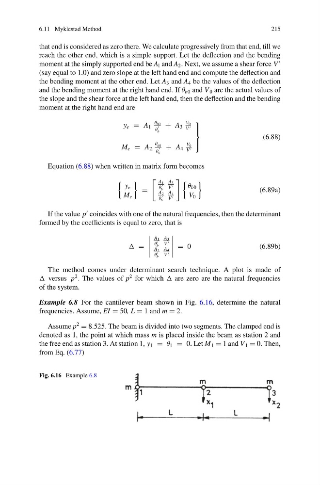
Example 6.8 For the cantilever beam shown in Fig. 6.16, determine the natural
frequencies. Assume, EI = 50, L = 1 and m = 2.
Assume p
2
= 8.525. The beam is divided into two segments. The clamped end is
denoted as 1, the point at which mass m is placed inside the beam as station 2 and
the free end as station 3. At station 1, y 1 = θ 1 = 0. Let M 1 = 1 and V 1 = 0. Then,
from Eq. (6.77)
Fig. 6.16 Example 6.8
215
that end is considered as zero there. We calculate progressively from that end, till we
reach the other end, which is a simple support. Let the deflection and the bending
moment at the simply supported end be A l and A 2 . Next, we assume a shear force V
(say equal to 1.0) and zero slope at the left hand end and compute the deflection and
the bending moment at the other end. Let A 3 and A 4 be the values of the deflection
and the bending moment at the right hand end. If θ b0 and V 0 are the actual values of
the slope and the shear force at the left hand end, then the deflection and the bending
moment at the right hand end are
y e = A 1
θ b0
θ
b
+ A 3
V 0
V
M e = A 2
θ b0
θ
b
+ A 4
V 0
V
⎫
⎪ ⎬
⎪ ⎭
(6.88)
Equation (6.88) when written in matrix form becomes
y e
M e
=
A 1
θ
b
A 3
V
A 2
θ
b
A 4
V
θ b0
V 0
(6.89a)
If the value p
coincides with one of the natural frequencies, then the determinant
formed by the coefficients is equal to zero, that is
=
A 1
θ
b
A 3
V
A 2
θ
b
A 4
V
= 0
(6.89b)
The method comes under determinant search technique. A plot is made of
versus p
2 . The values of p
2 for which are zero are the natural frequencies
of the system.
Example 6.8 For the cantilever beam shown in Fig. 6.16, determine the natural
frequencies. Assume, EI = 50, L = 1 and m = 2.
Assume p
2
= 8.525. The beam is divided into two segments. The clamped end is
denoted as 1, the point at which mass m is placed inside the beam as station 2 and
the free end as station 3. At station 1, y 1 = θ 1 = 0. Let M 1 = 1 and V 1 = 0. Then,
from Eq. (6.77)
Fig. 6.16 Example 6.8