

118
3 Forced Vibration of Single Degree of Freedom System
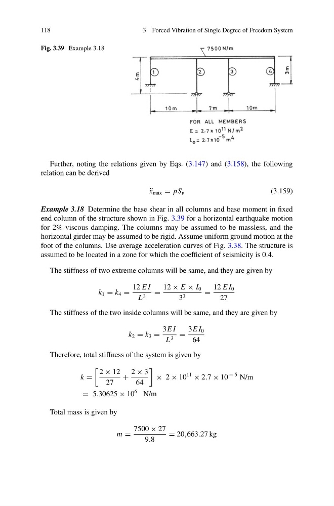
Fig. 3.39 Example 3.18
Further, noting the relations given by Eqs. (3.147) and (3.158), the following
relation can be derived
¨
x max = pS v
(3.159)
Example 3.18 Determine the base shear in all columns and base moment in fixed
end column of the structure shown in Fig. 3.39 for a horizontal earthquake motion
for 2% viscous damping. The columns may be assumed to be massless, and the
horizontal girder may be assumed to be rigid. Assume uniform ground motion at the
foot of the columns. Use average acceleration curves of Fig. 3.38. The structure is
assumed to be located in a zone for which the coefficient of seismicity is 0.4.
The stiffness of two extreme columns will be same, and they are given by
k 1 = k 4 =
12 E I
L 3 =
12 × E × I 0
3 3
=
12 E I 0
27
The stiffness of the two inside columns will be same, and they are given by
k 2 = k 3 =
3E I
L 3 =
3E I 0
64
Therefore, total stiffness of the system is given by
k =
2 × 12
27
+
2 × 3
64
× 2 × 10
11
× 2.7 × 10
− 5 N/m
= 5.30625 × 10
6 N/m
Total mass is given by
m =
7500 × 27
9.8
= 20,663.27 kg
3 Forced Vibration of Single Degree of Freedom System
Fig. 3.39 Example 3.18
Further, noting the relations given by Eqs. (3.147) and (3.158), the following
relation can be derived
¨
x max = pS v
(3.159)
Example 3.18 Determine the base shear in all columns and base moment in fixed
end column of the structure shown in Fig. 3.39 for a horizontal earthquake motion
for 2% viscous damping. The columns may be assumed to be massless, and the
horizontal girder may be assumed to be rigid. Assume uniform ground motion at the
foot of the columns. Use average acceleration curves of Fig. 3.38. The structure is
assumed to be located in a zone for which the coefficient of seismicity is 0.4.
The stiffness of two extreme columns will be same, and they are given by
k 1 = k 4 =
12 E I
L 3 =
12 × E × I 0
3 3
=
12 E I 0
27
The stiffness of the two inside columns will be same, and they are given by
k 2 = k 3 =
3E I
L 3 =
3E I 0
64
Therefore, total stiffness of the system is given by
k =
2 × 12
27
+
2 × 3
64
× 2 × 10
11
× 2.7 × 10
− 5 N/m
= 5.30625 × 10
6 N/m
Total mass is given by
m =
7500 × 27
9.8
= 20,663.27 kg