

244
D. Sen et al.
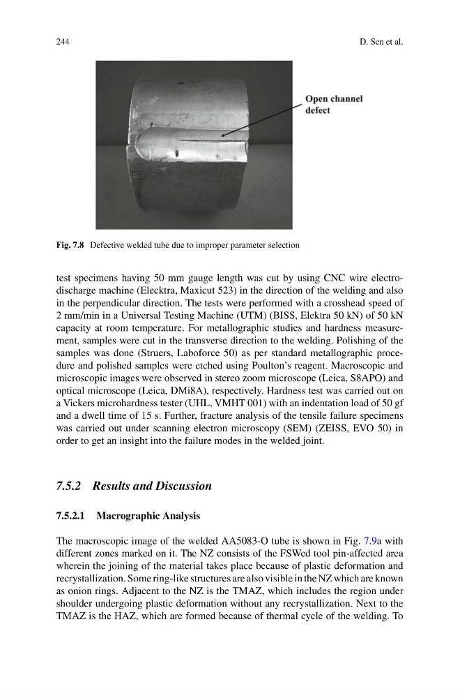
Fig. 7.8 Defective welded tube due to improper parameter selection
test specimens having 50 mm gauge length was cut by using CNC wire electrodischarge machine (Elecktra, Maxicut 523) in the direction of the welding and also
in the perpendicular direction. The tests were performed with a crosshead speed of
2 mm/min in a Universal Testing Machine (UTM) (BISS, Elektra 50 kN) of 50 kN
capacity at room temperature. For metallographic studies and hardness measurement, samples were cut in the transverse direction to the welding. Polishing of the
samples was done (Struers, Laboforce 50) as per standard metallographic procedure and polished samples were etched using Poulton’s reagent. Macroscopic and
microscopic images were observed in stereo zoom microscope (Leica, S8APO) and
optical microscope (Leica, DMi8A), respectively. Hardness test was carried out on
a Vickers microhardness tester (UHL, VMHT 001) with an indentation load of 50 gf
and a dwell time of 15 s. Further, fracture analysis of the tensile failure specimens
was carried out under scanning electron microscopy (SEM) (ZEISS, EVO 50) in
order to get an insight into the failure modes in the welded joint.
7.5.2 Results and Discussion
7.5.2.1 Macrographic Analysis
The macroscopic image of the welded AA5083-O tube is shown in Fig. 7.9a with
different zones marked on it. The NZ consists of the FSWed tool pin-affected area
wherein the joining of the material takes place because of plastic deformation and
recrystallization. Some ring-like structures are also visible in the NZ which are known
as onion rings. Adjacent to the NZ is the TMAZ, which includes the region under
shoulder undergoing plastic deformation without any recrystallization. Next to the
TMAZ is the HAZ, which are formed because of thermal cycle of the welding. To
D. Sen et al.
Fig. 7.8 Defective welded tube due to improper parameter selection
test specimens having 50 mm gauge length was cut by using CNC wire electrodischarge machine (Elecktra, Maxicut 523) in the direction of the welding and also
in the perpendicular direction. The tests were performed with a crosshead speed of
2 mm/min in a Universal Testing Machine (UTM) (BISS, Elektra 50 kN) of 50 kN
capacity at room temperature. For metallographic studies and hardness measurement, samples were cut in the transverse direction to the welding. Polishing of the
samples was done (Struers, Laboforce 50) as per standard metallographic procedure and polished samples were etched using Poulton’s reagent. Macroscopic and
microscopic images were observed in stereo zoom microscope (Leica, S8APO) and
optical microscope (Leica, DMi8A), respectively. Hardness test was carried out on
a Vickers microhardness tester (UHL, VMHT 001) with an indentation load of 50 gf
and a dwell time of 15 s. Further, fracture analysis of the tensile failure specimens
was carried out under scanning electron microscopy (SEM) (ZEISS, EVO 50) in
order to get an insight into the failure modes in the welded joint.
7.5.2 Results and Discussion
7.5.2.1 Macrographic Analysis
The macroscopic image of the welded AA5083-O tube is shown in Fig. 7.9a with
different zones marked on it. The NZ consists of the FSWed tool pin-affected area
wherein the joining of the material takes place because of plastic deformation and
recrystallization. Some ring-like structures are also visible in the NZ which are known
as onion rings. Adjacent to the NZ is the TMAZ, which includes the region under
shoulder undergoing plastic deformation without any recrystallization. Next to the
TMAZ is the HAZ, which are formed because of thermal cycle of the welding. To