

208
S. S. Nayak et al.
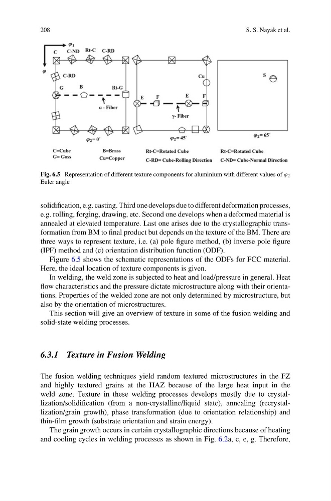
Fig. 6.5 Representation of different texture components for aluminium with different values of ϕ 2
Euler angle
solidification, e.g. casting. Third one develops due to different deformation processes,
e.g. rolling, forging, drawing, etc. Second one develops when a deformed material is
annealed at elevated temperature. Last one arises due to the crystallographic transformation from BM to final product but depends on the texture of the BM. There are
three ways to represent texture, i.e. (a) pole figure method, (b) inverse pole figure
(IPF) method and (c) orientation distribution function (ODF).
Figure 6.5 shows the schematic representations of the ODFs for FCC material.
Here, the ideal location of texture components is given.
In welding, the weld zone is subjected to heat and load/pressure in general. Heat
flow characteristics and the pressure dictate microstructure along with their orientations. Properties of the welded zone are not only determined by microstructure, but
also by the orientation of microstructures.
This section will give an overview of texture in some of the fusion welding and
solid-state welding processes.
6.3.1 Texture in Fusion Welding
The fusion welding techniques yield random textured microstructures in the FZ
and highly textured grains at the HAZ because of the large heat input in the
weld zone. Texture in these welding processes develops mostly due to crystallization/solidification (from a non-crystalline/liquid state), annealing (recrystallization/grain growth), phase transformation (due to orientation relationship) and
thin-film growth (substrate orientation and strain energy).
The grain growth occurs in certain crystallographic directions because of heating
and cooling cycles in welding processes as shown in Fig. 6.2a, c, e, g. Therefore,
S. S. Nayak et al.
Fig. 6.5 Representation of different texture components for aluminium with different values of ϕ 2
Euler angle
solidification, e.g. casting. Third one develops due to different deformation processes,
e.g. rolling, forging, drawing, etc. Second one develops when a deformed material is
annealed at elevated temperature. Last one arises due to the crystallographic transformation from BM to final product but depends on the texture of the BM. There are
three ways to represent texture, i.e. (a) pole figure method, (b) inverse pole figure
(IPF) method and (c) orientation distribution function (ODF).
Figure 6.5 shows the schematic representations of the ODFs for FCC material.
Here, the ideal location of texture components is given.
In welding, the weld zone is subjected to heat and load/pressure in general. Heat
flow characteristics and the pressure dictate microstructure along with their orientations. Properties of the welded zone are not only determined by microstructure, but
also by the orientation of microstructures.
This section will give an overview of texture in some of the fusion welding and
solid-state welding processes.
6.3.1 Texture in Fusion Welding
The fusion welding techniques yield random textured microstructures in the FZ
and highly textured grains at the HAZ because of the large heat input in the
weld zone. Texture in these welding processes develops mostly due to crystallization/solidification (from a non-crystalline/liquid state), annealing (recrystallization/grain growth), phase transformation (due to orientation relationship) and
thin-film growth (substrate orientation and strain energy).
The grain growth occurs in certain crystallographic directions because of heating
and cooling cycles in welding processes as shown in Fig. 6.2a, c, e, g. Therefore,