

3 Modeling of Friction Stir Welding Processes
93
3.2.1 Working Principle
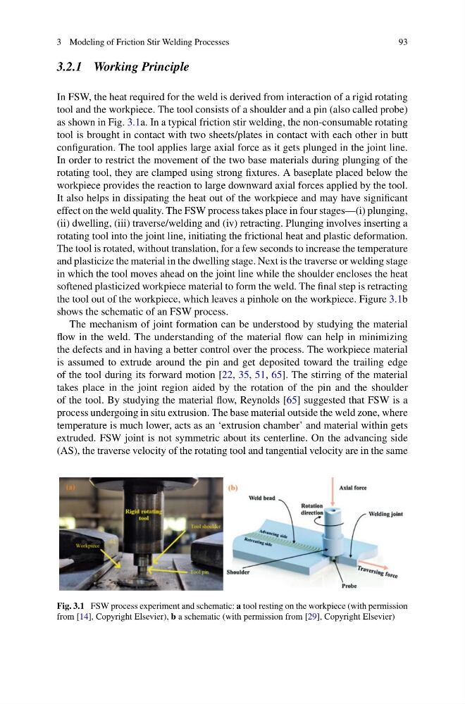
In FSW, the heat required for the weld is derived from interaction of a rigid rotating
tool and the workpiece. The tool consists of a shoulder and a pin (also called probe)
as shown in Fig. 3.1a. In a typical friction stir welding, the non-consumable rotating
tool is brought in contact with two sheets/plates in contact with each other in butt
configuration. The tool applies large axial force as it gets plunged in the joint line.
In order to restrict the movement of the two base materials during plunging of the
rotating tool, they are clamped using strong fixtures. A baseplate placed below the
workpiece provides the reaction to large downward axial forces applied by the tool.
It also helps in dissipating the heat out of the workpiece and may have significant
effect on the weld quality. The FSW process takes place in four stages—(i) plunging,
(ii) dwelling, (iii) traverse/welding and (iv) retracting. Plunging involves inserting a
rotating tool into the joint line, initiating the frictional heat and plastic deformation.
The tool is rotated, without translation, for a few seconds to increase the temperature
and plasticize the material in the dwelling stage. Next is the traverse or welding stage
in which the tool moves ahead on the joint line while the shoulder encloses the heat
softened plasticized workpiece material to form the weld. The final step is retracting
the tool out of the workpiece, which leaves a pinhole on the workpiece. Figure 3.1b
shows the schematic of an FSW process.
The mechanism of joint formation can be understood by studying the material
flow in the weld. The understanding of the material flow can help in minimizing
the defects and in having a better control over the process. The workpiece material
is assumed to extrude around the pin and get deposited toward the trailing edge
of the tool during its forward motion [22, 35, 51, 65]. The stirring of the material
takes place in the joint region aided by the rotation of the pin and the shoulder
of the tool. By studying the material flow, Reynolds [65] suggested that FSW is a
process undergoing in situ extrusion. The base material outside the weld zone, where
temperature is much lower, acts as an ‘extrusion chamber’ and material within gets
extruded. FSW joint is not symmetric about its centerline. On the advancing side
(AS), the traverse velocity of the rotating tool and tangential velocity are in the same
Fig. 3.1 FSW process experiment and schematic: a tool resting on the workpiece (with permission
from [14], Copyright Elsevier), b a schematic (with permission from [29], Copyright Elsevier)
93
3.2.1 Working Principle
In FSW, the heat required for the weld is derived from interaction of a rigid rotating
tool and the workpiece. The tool consists of a shoulder and a pin (also called probe)
as shown in Fig. 3.1a. In a typical friction stir welding, the non-consumable rotating
tool is brought in contact with two sheets/plates in contact with each other in butt
configuration. The tool applies large axial force as it gets plunged in the joint line.
In order to restrict the movement of the two base materials during plunging of the
rotating tool, they are clamped using strong fixtures. A baseplate placed below the
workpiece provides the reaction to large downward axial forces applied by the tool.
It also helps in dissipating the heat out of the workpiece and may have significant
effect on the weld quality. The FSW process takes place in four stages—(i) plunging,
(ii) dwelling, (iii) traverse/welding and (iv) retracting. Plunging involves inserting a
rotating tool into the joint line, initiating the frictional heat and plastic deformation.
The tool is rotated, without translation, for a few seconds to increase the temperature
and plasticize the material in the dwelling stage. Next is the traverse or welding stage
in which the tool moves ahead on the joint line while the shoulder encloses the heat
softened plasticized workpiece material to form the weld. The final step is retracting
the tool out of the workpiece, which leaves a pinhole on the workpiece. Figure 3.1b
shows the schematic of an FSW process.
The mechanism of joint formation can be understood by studying the material
flow in the weld. The understanding of the material flow can help in minimizing
the defects and in having a better control over the process. The workpiece material
is assumed to extrude around the pin and get deposited toward the trailing edge
of the tool during its forward motion [22, 35, 51, 65]. The stirring of the material
takes place in the joint region aided by the rotation of the pin and the shoulder
of the tool. By studying the material flow, Reynolds [65] suggested that FSW is a
process undergoing in situ extrusion. The base material outside the weld zone, where
temperature is much lower, acts as an ‘extrusion chamber’ and material within gets
extruded. FSW joint is not symmetric about its centerline. On the advancing side
(AS), the traverse velocity of the rotating tool and tangential velocity are in the same
Fig. 3.1 FSW process experiment and schematic: a tool resting on the workpiece (with permission
from [14], Copyright Elsevier), b a schematic (with permission from [29], Copyright Elsevier)