

60
3 Analysis of Strain
ε i j =
⎡
⎣
ε x ε xy ε xz
ε yx ε y ε yz
ε zx ε zy ε z
⎤
⎦
(3.11)
ε i j =
⎡
⎣
ε x
1
2
γ xy
1
2
γ xz
1
2
γ yx ε y
1
2
γ yz
1
2
γ zx
1
2
γ zy ε z
⎤
⎦
(3.12)
3.6 Rotations
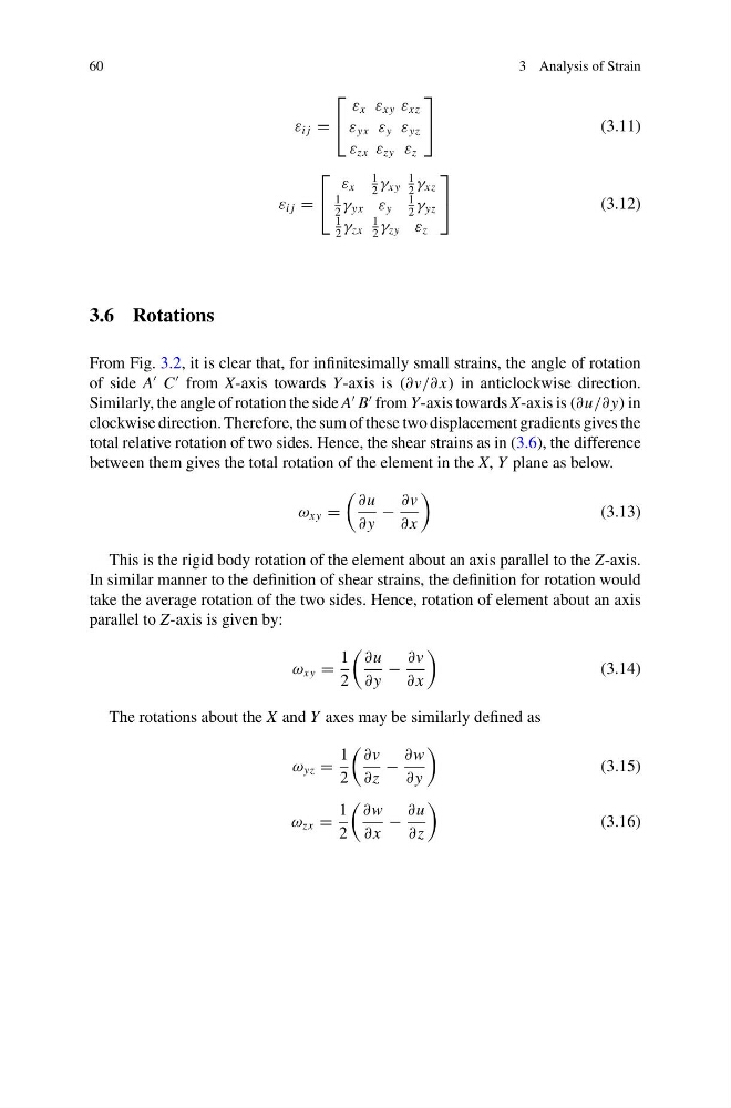
From Fig. 3.2, it is clear that, for infinitesimally small strains, the angle of rotation
of side A
C
from X-axis towards Y-axis is (∂v/∂ x) in anticlockwise direction.
Similarly, the angle of rotation the side A
B
from Y-axis towards X-axis is (∂u/∂ y) in
clockwise direction. Therefore, the sum of these two displacement gradients gives the
total relative rotation of two sides. Hence, the shear strains as in (3.6), the difference
between them gives the total rotation of the element in the X, Y plane as below.
ω xy =
∂u
∂ y
−
∂v
∂ x
(3.13)
This is the rigid body rotation of the element about an axis parallel to the Z-axis.
In similar manner to the definition of shear strains, the definition for rotation would
take the average rotation of the two sides. Hence, rotation of element about an axis
parallel to Z-axis is given by:
ω xy =
1
2
∂u
∂ y
−
∂v
∂ x
(3.14)
The rotations about the X and Y axes may be similarly defined as
ω yz =
1
2
∂v
∂z
−
∂w
∂ y
(3.15)
ω zx =
1
2
∂w
∂ x
−
∂u
∂z
(3.16)
3 Analysis of Strain
ε i j =
⎡
⎣
ε x ε xy ε xz
ε yx ε y ε yz
ε zx ε zy ε z
⎤
⎦
(3.11)
ε i j =
⎡
⎣
ε x
1
2
γ xy
1
2
γ xz
1
2
γ yx ε y
1
2
γ yz
1
2
γ zx
1
2
γ zy ε z
⎤
⎦
(3.12)
3.6 Rotations
From Fig. 3.2, it is clear that, for infinitesimally small strains, the angle of rotation
of side A
C
from X-axis towards Y-axis is (∂v/∂ x) in anticlockwise direction.
Similarly, the angle of rotation the side A
B
from Y-axis towards X-axis is (∂u/∂ y) in
clockwise direction. Therefore, the sum of these two displacement gradients gives the
total relative rotation of two sides. Hence, the shear strains as in (3.6), the difference
between them gives the total rotation of the element in the X, Y plane as below.
ω xy =
∂u
∂ y
−
∂v
∂ x
(3.13)
This is the rigid body rotation of the element about an axis parallel to the Z-axis.
In similar manner to the definition of shear strains, the definition for rotation would
take the average rotation of the two sides. Hence, rotation of element about an axis
parallel to Z-axis is given by:
ω xy =
1
2
∂u
∂ y
−
∂v
∂ x
(3.14)
The rotations about the X and Y axes may be similarly defined as
ω yz =
1
2
∂v
∂z
−
∂w
∂ y
(3.15)
ω zx =
1
2
∂w
∂ x
−
∂u
∂z
(3.16)