

30
2 Analysis of Stress
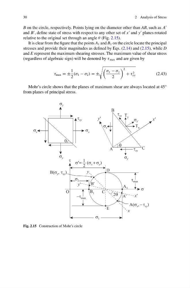
B on the circle, respectively. Points lying on the diameter other than AB, such as A
and B
, define state of stress with respect to any other set of x
and y
planes rotated
relative to the original set through an angle θ (Fig. 2.15).
It is clear from the figure that the points A 1 and B 1 on the circle locate the principal
stresses and provide their magnitudes as defined by Eqs. (2.14) and (2.15), while D
and E represent the maximum shearing stresses. The maximum value of shear stress
(regardless of algebraic sign) will be denoted by τ max and are given by
τ max = ±
1
2
(σ 1 − σ 2 ) = ±
σ x − σ y
2
2
+ τ 2
xy
(2.43)
Mohr’s circle shows that the planes of maximum shear are always located at 45°
from planes of principal stress.
Fig. 2.15 Construction of Mohr’s circle
2 Analysis of Stress
B on the circle, respectively. Points lying on the diameter other than AB, such as A
and B
, define state of stress with respect to any other set of x
and y
planes rotated
relative to the original set through an angle θ (Fig. 2.15).
It is clear from the figure that the points A 1 and B 1 on the circle locate the principal
stresses and provide their magnitudes as defined by Eqs. (2.14) and (2.15), while D
and E represent the maximum shearing stresses. The maximum value of shear stress
(regardless of algebraic sign) will be denoted by τ max and are given by
τ max = ±
1
2
(σ 1 − σ 2 ) = ±
σ x − σ y
2
2
+ τ 2
xy
(2.43)
Mohr’s circle shows that the planes of maximum shear are always located at 45°
from planes of principal stress.
Fig. 2.15 Construction of Mohr’s circle