

2.13 Stress Components on Oblique Plane (Stress Transformation)
21
Equations (2.27)–(2.27e) represent expressions transforming the quantities
σ x , σ y , τ xy , τ yz , τ xz to completely define the state of stress.
It is to be noted that because, X
, Y
and Z
are orthogonal, the nine direction
cosines must satisfy trigonometric relations of the following form.
l
2
i + m
2
i + n
2
i = 1 (i = 1, 2, 3)
and
l 1 l 2 + m 1 m 2 + n 1 n 2 = 0
l 2 l 3 + m 2 m 3 + n 2 n 3 = 0
l 1 l 3 + m 1 m 3 + n 1 n 3 = 0
(2.27f)
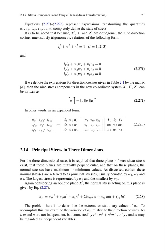
If we denote the expressions for direction cosines given in Table 2.1 by the matrix
[a], then the nine stress components in the new co-ordinate system X
, Y
, Z
, can
be written as
σ
= [a][σ ][a]
T
(2.27f)
In other words, in an expanded form:
⎡
⎣
σ x
τ x
y
τ x
z
τ y
x
σ y
τ y
z
τ z
x
τ z
y
σ z
⎤
⎦ =
⎡
⎣
1 m 1 n 1
2 m 2 n 2
3 m 3 n 3
⎤
⎦
⎡
⎣
σ x τ xy τ xz
τ yx σ y τ y z
τ zx τ z y σ z
⎤
⎦
⎡
⎣
1 2 3
m 1 m 2 m 3
n 1 n 2 n 3
⎤
⎦
(2.27h)
2.14 Principal Stress in Three Dimensions
For the three-dimensional case, it is required that three planes of zero shear stress
exist, that these planes are mutually perpendicular, and that on these planes, the
normal stresses have maximum or minimum values. As discussed earlier, these
normal stresses are referred to as principal stresses, usually denoted by σ 1 , σ 2 and
σ 3 . The largest stress is represented by σ 1 and the smallest by σ 3 .
Again considering an oblique plane X
, the normal stress acting on this plane is
given by Eq. (2.27).
σ x = σ x l
2
+ σ y m
2
+ σ z n
2
+ 2(τ xy lm + τ yz mn + τ xz ln)
(2.28)
The problem here is to determine the extreme or stationary values of σ x . To
accomplish this, we examine the variation of σ x relative to the direction cosines. As
l, m and n are not independent, but connected by l
2 + m
2
+ n
2
= 1, only l and m may
be regarded as independent variables.
21
Equations (2.27)–(2.27e) represent expressions transforming the quantities
σ x , σ y , τ xy , τ yz , τ xz to completely define the state of stress.
It is to be noted that because, X
, Y
and Z
are orthogonal, the nine direction
cosines must satisfy trigonometric relations of the following form.
l
2
i + m
2
i + n
2
i = 1 (i = 1, 2, 3)
and
l 1 l 2 + m 1 m 2 + n 1 n 2 = 0
l 2 l 3 + m 2 m 3 + n 2 n 3 = 0
l 1 l 3 + m 1 m 3 + n 1 n 3 = 0
(2.27f)
If we denote the expressions for direction cosines given in Table 2.1 by the matrix
[a], then the nine stress components in the new co-ordinate system X
, Y
, Z
, can
be written as
σ
= [a][σ ][a]
T
(2.27f)
In other words, in an expanded form:
⎡
⎣
σ x
τ x
y
τ x
z
τ y
x
σ y
τ y
z
τ z
x
τ z
y
σ z
⎤
⎦ =
⎡
⎣
1 m 1 n 1
2 m 2 n 2
3 m 3 n 3
⎤
⎦
⎡
⎣
σ x τ xy τ xz
τ yx σ y τ y z
τ zx τ z y σ z
⎤
⎦
⎡
⎣
1 2 3
m 1 m 2 m 3
n 1 n 2 n 3
⎤
⎦
(2.27h)
2.14 Principal Stress in Three Dimensions
For the three-dimensional case, it is required that three planes of zero shear stress
exist, that these planes are mutually perpendicular, and that on these planes, the
normal stresses have maximum or minimum values. As discussed earlier, these
normal stresses are referred to as principal stresses, usually denoted by σ 1 , σ 2 and
σ 3 . The largest stress is represented by σ 1 and the smallest by σ 3 .
Again considering an oblique plane X
, the normal stress acting on this plane is
given by Eq. (2.27).
σ x = σ x l
2
+ σ y m
2
+ σ z n
2
+ 2(τ xy lm + τ yz mn + τ xz ln)
(2.28)
The problem here is to determine the extreme or stationary values of σ x . To
accomplish this, we examine the variation of σ x relative to the direction cosines. As
l, m and n are not independent, but connected by l
2 + m
2
+ n
2
= 1, only l and m may
be regarded as independent variables.