

2.3 Concept of Direct Stress and Shear Stress
9
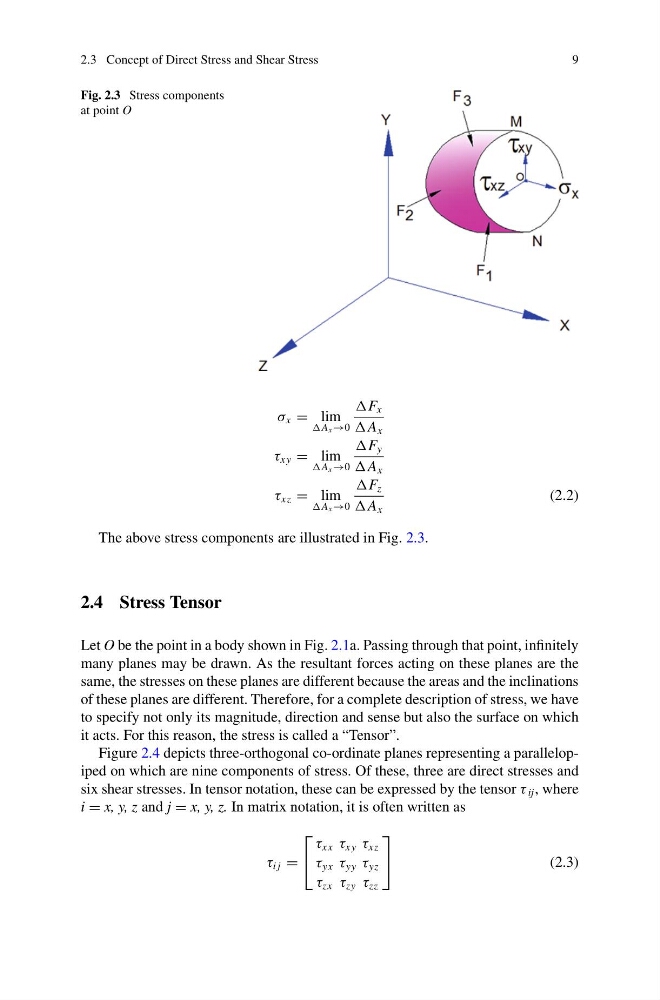
Fig. 2.3 Stress components
at point O
σ x = lim
A x →0
F x
A x
τ xy = lim
A x →0
F y
A x
τ xz = lim
A x →0
F z
A x
(2.2)
The above stress components are illustrated in Fig. 2.3.
2.4 Stress Tensor
Let O be the point in a body shown in Fig. 2.1a. Passing through that point, infinitely
many planes may be drawn. As the resultant forces acting on these planes are the
same, the stresses on these planes are different because the areas and the inclinations
of these planes are different. Therefore, for a complete description of stress, we have
to specify not only its magnitude, direction and sense but also the surface on which
it acts. For this reason, the stress is called a “Tensor”.
Figure 2.4 depicts three-orthogonal co-ordinate planes representing a parallelopiped on which are nine components of stress. Of these, three are direct stresses and
six shear stresses. In tensor notation, these can be expressed by the tensor τ ij , where
i = x, y, z and j = x, y, z. In matrix notation, it is often written as
τ i j =
⎡
⎣
τ xx τ xy τ xz
τ yx τ yy τ yz
τ zx τ zy τ zz
⎤
⎦
(2.3)
9
Fig. 2.3 Stress components
at point O
σ x = lim
A x →0
F x
A x
τ xy = lim
A x →0
F y
A x
τ xz = lim
A x →0
F z
A x
(2.2)
The above stress components are illustrated in Fig. 2.3.
2.4 Stress Tensor
Let O be the point in a body shown in Fig. 2.1a. Passing through that point, infinitely
many planes may be drawn. As the resultant forces acting on these planes are the
same, the stresses on these planes are different because the areas and the inclinations
of these planes are different. Therefore, for a complete description of stress, we have
to specify not only its magnitude, direction and sense but also the surface on which
it acts. For this reason, the stress is called a “Tensor”.
Figure 2.4 depicts three-orthogonal co-ordinate planes representing a parallelopiped on which are nine components of stress. Of these, three are direct stresses and
six shear stresses. In tensor notation, these can be expressed by the tensor τ ij , where
i = x, y, z and j = x, y, z. In matrix notation, it is often written as
τ i j =
⎡
⎣
τ xx τ xy τ xz
τ yx τ yy τ yz
τ zx τ zy τ zz
⎤
⎦
(2.3)