

64
3 Subsonic Wind Tunnels
(a) Test section with UAV model
(Unmanned Aerial Vehicle)
(b) Settling chamber
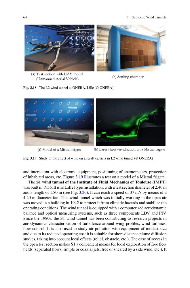
Fig. 3.18 The L2 wind tunnel at ONERA, Lille (© ONERA)
(a) Model of a Mistral frigate
(b) Laser sheet visualisation on a Mistral frigate
Fig. 3.19 Study of the effect of wind on aircraft carriers in L2 wind tunnel (© ONERA)
and interaction with electronic equipment, positioning of anemometers, protection
of inhabited areas, etc. Figure 3.19 illustrates a test on a model of a Mistral frigate.
The S1 wind tunnel of the Institute of Fluid Mechanics of Toulouse (IMFT)
was built in 1936. It is an Eiffel type installation, with a test section diameter of 2.40 m
and a length of 1.80 m (see Fig. 3.20). It can reach a speed of 37 m/s by means of a
4.20 m diameter fan. This wind tunnel which was initially working in the open air
was moved in a building in 1942 to protect it from climatic hazards and stabilise the
operating conditions. The wind tunnel is equipped with a computerised aerodynamic
balance and optical measuring systems, such as three components LDV and PIV.
Since the 1980s, the S1 wind tunnel has been contributing to research projects in
aerodynamics characterisation of turbulence around wing profiles, wind turbines,
flow control. It is also used to study air pollution with equipment of modest size
and due to its reduced operating cost it is suitable for short-distance plume diffusion
studies, taking into account local effects (relief, obstacle, etc.). The ease of access in
the open test section makes S1 a convenient means for local exploration of free flow
fields (separated flows, simple or coaxial jets, free or sheared by a side wind, etc.). It
3 Subsonic Wind Tunnels
(a) Test section with UAV model
(Unmanned Aerial Vehicle)
(b) Settling chamber
Fig. 3.18 The L2 wind tunnel at ONERA, Lille (© ONERA)
(a) Model of a Mistral frigate
(b) Laser sheet visualisation on a Mistral frigate
Fig. 3.19 Study of the effect of wind on aircraft carriers in L2 wind tunnel (© ONERA)
and interaction with electronic equipment, positioning of anemometers, protection
of inhabited areas, etc. Figure 3.19 illustrates a test on a model of a Mistral frigate.
The S1 wind tunnel of the Institute of Fluid Mechanics of Toulouse (IMFT)
was built in 1936. It is an Eiffel type installation, with a test section diameter of 2.40 m
and a length of 1.80 m (see Fig. 3.20). It can reach a speed of 37 m/s by means of a
4.20 m diameter fan. This wind tunnel which was initially working in the open air
was moved in a building in 1942 to protect it from climatic hazards and stabilise the
operating conditions. The wind tunnel is equipped with a computerised aerodynamic
balance and optical measuring systems, such as three components LDV and PIV.
Since the 1980s, the S1 wind tunnel has been contributing to research projects in
aerodynamics characterisation of turbulence around wing profiles, wind turbines,
flow control. It is also used to study air pollution with equipment of modest size
and due to its reduced operating cost it is suitable for short-distance plume diffusion
studies, taking into account local effects (relief, obstacle, etc.). The ease of access in
the open test section makes S1 a convenient means for local exploration of free flow
fields (separated flows, simple or coaxial jets, free or sheared by a side wind, etc.). It