

6.3 Hypersonic “Hot” or Hyper-enthalpic Wind Tunnels
163
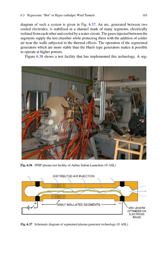
diagram of such a system is given in Fig. 6.37. An arc, generated between two
cooled electrodes, is stabilised in a channel made of many segments, electrically
isolated from each other and cooled by a water circuit. The gases injected between the
segments supply the test chamber while protecting them with the addition of colder
air near the walls subjected to the thermal effects. The operation of the segmented
generators which are more stable than the Huels type generators makes it possible
to operate at higher powers.
Figure 6.38 shows a test facility that has implemented this technology. A segFig. 6.36 JPHP plasma test facility of Airbus Safran Launchers (© ASL)
Fig. 6.37 Schematic diagram of segmented plasma generator technology (© ASL)
163
diagram of such a system is given in Fig. 6.37. An arc, generated between two
cooled electrodes, is stabilised in a channel made of many segments, electrically
isolated from each other and cooled by a water circuit. The gases injected between the
segments supply the test chamber while protecting them with the addition of colder
air near the walls subjected to the thermal effects. The operation of the segmented
generators which are more stable than the Huels type generators makes it possible
to operate at higher powers.
Figure 6.38 shows a test facility that has implemented this technology. A segFig. 6.36 JPHP plasma test facility of Airbus Safran Launchers (© ASL)
Fig. 6.37 Schematic diagram of segmented plasma generator technology (© ASL)