

6.3 Hypersonic “Hot” or Hyper-enthalpic Wind Tunnels
151
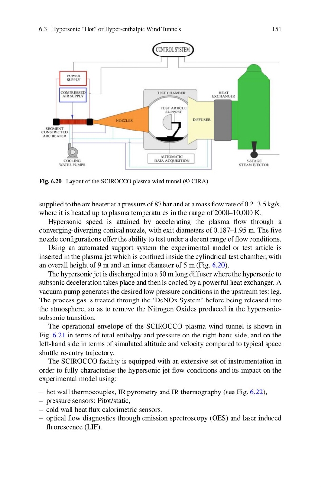
Fig. 6.20 Layout of the SCIROCCO plasma wind tunnel (© CIRA)
supplied to the arc heater at a pressure of 87 bar and at a mass flow rate of 0.2–3.5 kg/s,
where it is heated up to plasma temperatures in the range of 2000–10,000 K.
Hypersonic speed is attained by accelerating the plasma flow through a
converging-diverging conical nozzle, with exit diameters of 0.187–1.95 m. The five
nozzle configurations offer the ability to test under a decent range of flow conditions.
Using an automated support system the experimental model or test article is
inserted in the plasma jet which is confined inside the cylindrical test chamber, with
an overall height of 9 m and an inner diameter of 5 m (Fig. 6.20).
The hypersonic jet is discharged into a 50 m long diffuser where the hypersonic to
subsonic deceleration takes place and then is cooled by a powerful heat exchanger. A
vacuum pump generates the desired low pressure conditions in the upstream test leg.
The process gas is treated through the ‘DeNOx System’ before being released into
the atmosphere, so as to remove the Nitrogen Oxides produced in the hypersonicsubsonic transition.
The operational envelope of the SCIROCCO plasma wind tunnel is shown in
Fig. 6.21 in terms of total enthalpy and pressure on the right-hand side, and on the
left-hand side in terms of simulated altitude and velocity compared to typical space
shuttle re-entry trajectory.
The SCIROCCO facility is equipped with an extensive set of instrumentation in
order to fully characterise the hypersonic jet flow conditions and its impact on the
experimental model using:
– hot wall thermocouples, IR pyrometry and IR thermography (see Fig. 6.22),
– pressure sensors: Pitot/static,
– cold wall heat flux calorimetric sensors,
– optical flow diagnostics through emission spectroscopy (OES) and laser induced
fluorescence (LIF).
151
Fig. 6.20 Layout of the SCIROCCO plasma wind tunnel (© CIRA)
supplied to the arc heater at a pressure of 87 bar and at a mass flow rate of 0.2–3.5 kg/s,
where it is heated up to plasma temperatures in the range of 2000–10,000 K.
Hypersonic speed is attained by accelerating the plasma flow through a
converging-diverging conical nozzle, with exit diameters of 0.187–1.95 m. The five
nozzle configurations offer the ability to test under a decent range of flow conditions.
Using an automated support system the experimental model or test article is
inserted in the plasma jet which is confined inside the cylindrical test chamber, with
an overall height of 9 m and an inner diameter of 5 m (Fig. 6.20).
The hypersonic jet is discharged into a 50 m long diffuser where the hypersonic to
subsonic deceleration takes place and then is cooled by a powerful heat exchanger. A
vacuum pump generates the desired low pressure conditions in the upstream test leg.
The process gas is treated through the ‘DeNOx System’ before being released into
the atmosphere, so as to remove the Nitrogen Oxides produced in the hypersonicsubsonic transition.
The operational envelope of the SCIROCCO plasma wind tunnel is shown in
Fig. 6.21 in terms of total enthalpy and pressure on the right-hand side, and on the
left-hand side in terms of simulated altitude and velocity compared to typical space
shuttle re-entry trajectory.
The SCIROCCO facility is equipped with an extensive set of instrumentation in
order to fully characterise the hypersonic jet flow conditions and its impact on the
experimental model using:
– hot wall thermocouples, IR pyrometry and IR thermography (see Fig. 6.22),
– pressure sensors: Pitot/static,
– cold wall heat flux calorimetric sensors,
– optical flow diagnostics through emission spectroscopy (OES) and laser induced
fluorescence (LIF).