

6.2 Hypersonic “Cold” Wind Tunnels
139
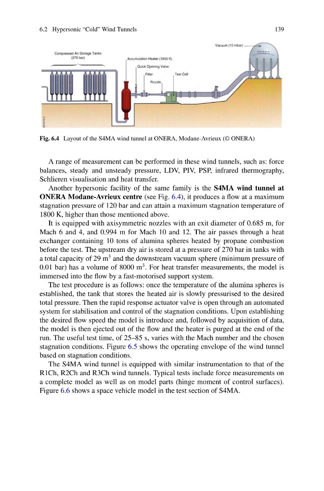
Fig. 6.4 Layout of the S4MA wind tunnel at ONERA, Modane-Avrieux (© ONERA)
A range of measurement can be performed in these wind tunnels, such as: force
balances, steady and unsteady pressure, LDV, PIV, PSP, infrared thermography,
Schlieren visualisation and heat transfer.
Another hypersonic facility of the same family is the S4MA wind tunnel at
ONERA Modane-Avrieux centre (see Fig. 6.4), it produces a flow at a maximum
stagnation pressure of 120 bar and can attain a maximum stagnation temperature of
1800 K, higher than those mentioned above.
It is equipped with axisymmetric nozzles with an exit diameter of 0.685 m, for
Mach 6 and 4, and 0.994 m for Mach 10 and 12. The air passes through a heat
exchanger containing 10 tons of alumina spheres heated by propane combustion
before the test. The upstream dry air is stored at a pressure of 270 bar in tanks with
a total capacity of 29 m
3 and the downstream vacuum sphere (minimum pressure of
0.01 bar) has a volume of 8000 m
3 . For heat transfer measurements, the model is
immersed into the flow by a fast-motorised support system.
The test procedure is as follows: once the temperature of the alumina spheres is
established, the tank that stores the heated air is slowly pressurised to the desired
total pressure. Then the rapid response actuator valve is open through an automated
system for stabilisation and control of the stagnation conditions. Upon establishing
the desired flow speed the model is introduce and, followed by acquisition of data,
the model is then ejected out of the flow and the heater is purged at the end of the
run. The useful test time, of 25–85 s, varies with the Mach number and the chosen
stagnation conditions. Figure 6.5 shows the operating envelope of the wind tunnel
based on stagnation conditions.
The S4MA wind tunnel is equipped with similar instrumentation to that of the
R1Ch, R2Ch and R3Ch wind tunnels. Typical tests include force measurements on
a complete model as well as on model parts (hinge moment of control surfaces).
Figure 6.6 shows a space vehicle model in the test section of S4MA.
139
Fig. 6.4 Layout of the S4MA wind tunnel at ONERA, Modane-Avrieux (© ONERA)
A range of measurement can be performed in these wind tunnels, such as: force
balances, steady and unsteady pressure, LDV, PIV, PSP, infrared thermography,
Schlieren visualisation and heat transfer.
Another hypersonic facility of the same family is the S4MA wind tunnel at
ONERA Modane-Avrieux centre (see Fig. 6.4), it produces a flow at a maximum
stagnation pressure of 120 bar and can attain a maximum stagnation temperature of
1800 K, higher than those mentioned above.
It is equipped with axisymmetric nozzles with an exit diameter of 0.685 m, for
Mach 6 and 4, and 0.994 m for Mach 10 and 12. The air passes through a heat
exchanger containing 10 tons of alumina spheres heated by propane combustion
before the test. The upstream dry air is stored at a pressure of 270 bar in tanks with
a total capacity of 29 m
3 and the downstream vacuum sphere (minimum pressure of
0.01 bar) has a volume of 8000 m
3 . For heat transfer measurements, the model is
immersed into the flow by a fast-motorised support system.
The test procedure is as follows: once the temperature of the alumina spheres is
established, the tank that stores the heated air is slowly pressurised to the desired
total pressure. Then the rapid response actuator valve is open through an automated
system for stabilisation and control of the stagnation conditions. Upon establishing
the desired flow speed the model is introduce and, followed by acquisition of data,
the model is then ejected out of the flow and the heater is purged at the end of the
run. The useful test time, of 25–85 s, varies with the Mach number and the chosen
stagnation conditions. Figure 6.5 shows the operating envelope of the wind tunnel
based on stagnation conditions.
The S4MA wind tunnel is equipped with similar instrumentation to that of the
R1Ch, R2Ch and R3Ch wind tunnels. Typical tests include force measurements on
a complete model as well as on model parts (hinge moment of control surfaces).
Figure 6.6 shows a space vehicle model in the test section of S4MA.