

638
6 Reverse Engineering of Microcircuits
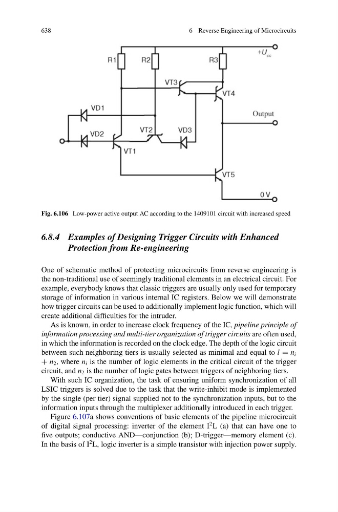
Fig. 6.106 Low-power active output AC according to the 1409101 circuit with increased speed
6.8.4 Examples of Designing Trigger Circuits with Enhanced
Protection from Re-engineering
One of schematic method of protecting microcircuits from reverse engineering is
the non-traditional use of seemingly traditional elements in an electrical circuit. For
example, everybody knows that classic triggers are usually only used for temporary
storage of information in various internal IC registers. Below we will demonstrate
how trigger circuits can be used to additionally implement logic function, which will
create additional difficulties for the intruder.
As is known, in order to increase clock frequency of the IC, pipeline principle of
information processing and multi-tier organization of trigger circuits are often used,
in which the information is recorded on the clock edge. The depth of the logic circuit
between such neighboring tiers is usually selected as minimal and equal to l = n i
+ n 2 , where n i is the number of logic elements in the critical circuit of the trigger
circuit, and n 2 is the number of logic gates between triggers of neighboring tiers.
With such IC organization, the task of ensuring uniform synchronization of all
LSIC triggers is solved due to the task that the write-inhibit mode is implemented
by the single (per tier) signal supplied not to the synchronization inputs, but to the
information inputs through the multiplexer additionally introduced in each trigger.
Figure 6.107a shows conventions of basic elements of the pipeline microcircuit
of digital signal processing: inverter of the element I
2 L (a) that can have one to
five outputs; conductive AND—conjunction (b); D-trigger—memory element (c).
In the basis of I
2 L, logic inverter is a simple transistor with injection power supply.