

4.2 Description of the First Documented Facts …
303
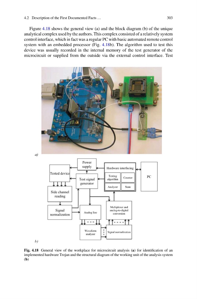
Figure 4.18 shows the general view (a) and the block diagram (b) of the unique
analytical complex used by the authors. This complex consisted of a relatively system
control interface, which in fact was a regular PC with basic automated remote control
system with an embedded processor (Fig. 4.18b). The algorithm used to test this
device was usually recorded in the internal memory of the test generator of the
microcircuit or supplied from the outside via the external control interface. Test
а)
b)
Power
supply
Tested device
Side channel
reading
Signal
normalization
Test signal
generator
PC
Hardware interfacing
Testing
algorithm
Analyzer
Counter
State
Analog line
Multiplexer and
analog-to-digital
conversion
Waveform
analyzer
Signal normalization
Fig. 4.18 General view of the workplace for microcircuit analysis (a) for identification of an
implemented hardware Trojan and the structural diagram of the working unit of the analysis system
(b)
303
Figure 4.18 shows the general view (a) and the block diagram (b) of the unique
analytical complex used by the authors. This complex consisted of a relatively system
control interface, which in fact was a regular PC with basic automated remote control
system with an embedded processor (Fig. 4.18b). The algorithm used to test this
device was usually recorded in the internal memory of the test generator of the
microcircuit or supplied from the outside via the external control interface. Test
а)
b)
Power
supply
Tested device
Side channel
reading
Signal
normalization
Test signal
generator
PC
Hardware interfacing
Testing
algorithm
Analyzer
Counter
State
Analog line
Multiplexer and
analog-to-digital
conversion
Waveform
analyzer
Signal normalization
Fig. 4.18 General view of the workplace for microcircuit analysis (a) for identification of an
implemented hardware Trojan and the structural diagram of the working unit of the analysis system
(b)