

68
G. Chakraborty and N. Jani
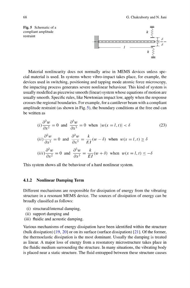
Fig. 5 Schematic of a
compliant amplitude
restraint
Material nonlinearity does not normally arise in MEMS devices unless special material is used. In systems where vibro-impact takes place, for example, the
devices used in switching, positioning and tapping mode atomic force microscopy,
the impacting process generates severe nonlinear behaviour. This kind of system is
usually modelled as piecewise smooth (linear) system whose equations of motion are
usually smooth. Specific rules, like Newtonian impact low, apply when the response
crosses the regional boundaries. For example, for a cantilever beam with a compliant
amplitude restraint (as shown in Fig. 5), the boundary conditions at the free end can
be written as
(i)
∂
2
w
∂x 2 = 0 and
∂
3
w
∂x 3 = 0 when |w(x = l, t)| < δ
(23)
(ii)
∂
2
w
∂x 2 = 0 and
∂
3
w
∂x 3 =
k
E I
(w − δ) when w(x = l, t) ≥ δ
(iii)
∂
2
w
∂x 2 = 0 and
∂
3
w
∂x 3 =
k
E I
(w + δ) when w(x = l, t) ≤ −δ
This system shows all the behaviour of a hard nonlinear system.
4.1.2 Nonlinear Damping Term
Different mechanisms are responsible for dissipation of energy from the vibrating
structure in a resonant MEMS device. The sources of dissipation of energy can be
broadly classified as follows:
(i) structural/internal damping,
(ii) support damping and
(iii) fluidic and acoustic damping.
Various mechanisms of energy dissipation have been identified within the structure
(bulk dissipation) [19, 20] or on its surface (surface dissipation) [21]. Of the former,
the thermoelastic dissipation is the most dominant. Usually the damping is treated
as linear. A major loss of energy from a resonatory microstructure takes place in
the fluidic medium surrounding the structure. In many situations, the vibrating body
is placed near a static structure. The fluid entrapped between these structure causes
G. Chakraborty and N. Jani
Fig. 5 Schematic of a
compliant amplitude
restraint
Material nonlinearity does not normally arise in MEMS devices unless special material is used. In systems where vibro-impact takes place, for example, the
devices used in switching, positioning and tapping mode atomic force microscopy,
the impacting process generates severe nonlinear behaviour. This kind of system is
usually modelled as piecewise smooth (linear) system whose equations of motion are
usually smooth. Specific rules, like Newtonian impact low, apply when the response
crosses the regional boundaries. For example, for a cantilever beam with a compliant
amplitude restraint (as shown in Fig. 5), the boundary conditions at the free end can
be written as
(i)
∂
2
w
∂x 2 = 0 and
∂
3
w
∂x 3 = 0 when |w(x = l, t)| < δ
(23)
(ii)
∂
2
w
∂x 2 = 0 and
∂
3
w
∂x 3 =
k
E I
(w − δ) when w(x = l, t) ≥ δ
(iii)
∂
2
w
∂x 2 = 0 and
∂
3
w
∂x 3 =
k
E I
(w + δ) when w(x = l, t) ≤ −δ
This system shows all the behaviour of a hard nonlinear system.
4.1.2 Nonlinear Damping Term
Different mechanisms are responsible for dissipation of energy from the vibrating
structure in a resonant MEMS device. The sources of dissipation of energy can be
broadly classified as follows:
(i) structural/internal damping,
(ii) support damping and
(iii) fluidic and acoustic damping.
Various mechanisms of energy dissipation have been identified within the structure
(bulk dissipation) [19, 20] or on its surface (surface dissipation) [21]. Of the former,
the thermoelastic dissipation is the most dominant. Usually the damping is treated
as linear. A major loss of energy from a resonatory microstructure takes place in
the fluidic medium surrounding the structure. In many situations, the vibrating body
is placed near a static structure. The fluid entrapped between these structure causes