

2 The Smart “Things” in IoT
75
2.5.3.3 Analog Outputs
Analog output is needed for several applications such as controlling motor speed.
MCUs are digital by nature and can generate either high or low voltage; however,
they are not able to produce a varying voltage (analog value). Therefore, it is
necessary to emulate varying voltage (analog value) by generating a series of voltage
at regular intervals but with different pulse widths, known as pulse width modulation
(PWM). PWM is a method for obtaining analog values utilizing digital means. The
voltage produced by PWM is often referred to as pseudo-analog voltage.
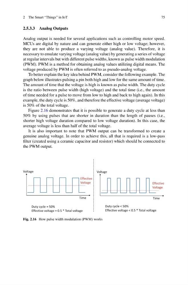
To better explain the key idea behind PWM, consider the following example. The
graph below illustrates pulsing a pin both high and low for the same amount of time.
The amount of time that the voltage is high is known as pulse width. The duty cycle
is the ratio between pulse width (high voltage) and the total time (i.e., the amount
of time needed for a pulse to move from low to high and back to high again). In this
example, the duty cycle is 50%, and therefore the effective voltage (average voltage)
is 50% of the total voltage.
Figure 2.16 demonstrates that it is possible to generate a duty cycle at less than
50% by using pulses that are shorter in duration than the length of pauses (i.e.,
shorter high voltage duration compared to low voltage duration). In this case, the
average voltage is less than half of the total voltage.
It is also important to note that PWM output can be transformed to create a
genuine analog voltage. In order to achieve this, all that is required is a low-pass
filter (created using a ceramic capacitor and resistor) which should be connected to
the PWM output.
Effective
Voltage
Time
Voltage
Effective
Voltage
Time
Voltage
Duty cycle = 50%
Effective voltage = 0.5 * Total voltage
Duty cycle < 50%
Effective voltage < 0.5 * Total voltage
Fig. 2.16 How pulse width modulation (PWM) works
75
2.5.3.3 Analog Outputs
Analog output is needed for several applications such as controlling motor speed.
MCUs are digital by nature and can generate either high or low voltage; however,
they are not able to produce a varying voltage (analog value). Therefore, it is
necessary to emulate varying voltage (analog value) by generating a series of voltage
at regular intervals but with different pulse widths, known as pulse width modulation
(PWM). PWM is a method for obtaining analog values utilizing digital means. The
voltage produced by PWM is often referred to as pseudo-analog voltage.
To better explain the key idea behind PWM, consider the following example. The
graph below illustrates pulsing a pin both high and low for the same amount of time.
The amount of time that the voltage is high is known as pulse width. The duty cycle
is the ratio between pulse width (high voltage) and the total time (i.e., the amount
of time needed for a pulse to move from low to high and back to high again). In this
example, the duty cycle is 50%, and therefore the effective voltage (average voltage)
is 50% of the total voltage.
Figure 2.16 demonstrates that it is possible to generate a duty cycle at less than
50% by using pulses that are shorter in duration than the length of pauses (i.e.,
shorter high voltage duration compared to low voltage duration). In this case, the
average voltage is less than half of the total voltage.
It is also important to note that PWM output can be transformed to create a
genuine analog voltage. In order to achieve this, all that is required is a low-pass
filter (created using a ceramic capacitor and resistor) which should be connected to
the PWM output.
Effective
Voltage
Time
Voltage
Effective
Voltage
Time
Voltage
Duty cycle = 50%
Effective voltage = 0.5 * Total voltage
Duty cycle < 50%
Effective voltage < 0.5 * Total voltage
Fig. 2.16 How pulse width modulation (PWM) works