

462
M. N. Bojnordi and P. Behnam
A
C
B
D
reduction units
m 0
m 1
m 0
Operation
m 1 m 0
01 01 Read A
01 10 Read B
01 11 Read A+B
10 01 Read C
10 10 Read D
10 11 Read C+D
11 01 Read A+C
11 10 Read B+D
11 11 Read A+B+C+D
data arrays
+
mode
(m)
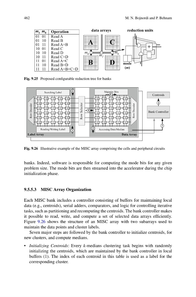
Fig. 9.25 Proposed configurable reduction tree for banks
Label Array
Data Array
Row Selector
Row Decoder
Searching Label
Accessing Data/Median
Majority Bits
Reading/Writing Label
Row Decoder
3
4
5
6
Bank Controller
Centroids
1
2
7
Fig. 9.26 Illustrative example of the MISC array comprising the cells and peripheral circuits
banks. Indeed, software is responsible for computing the mode bits for any given
problem size. The mode bits are then streamed into the accelerator during the chip
initialization phase.
9.5.5.3 MISC Array Organization
Each MISC bank includes a controller consisting of buffers for maintaining local
data (e.g., centroids), serial adders, comparators, and logic for controlling iterative
tasks, such as partitioning and recomputing the centroids. The bank controller makes
it possible to read, write, and compute a set of selected data arrays efficiently.
Figure 9.26 shows the structure of an MISC array with two subarrays used to
maintain the data points and cluster labels.
Seven major steps are followed by the bank controller to initialize centroids, for
new clusters, and compute medians.
• Initializing Centroids: Every k-medians clustering task begins with randomly
initializing the centroids, which are maintained by the bank controller in local
buffers (1). The index of each centroid in this table is used as a label for the
corresponding cluster.
M. N. Bojnordi and P. Behnam
A
C
B
D
reduction units
m 0
m 1
m 0
Operation
m 1 m 0
01 01 Read A
01 10 Read B
01 11 Read A+B
10 01 Read C
10 10 Read D
10 11 Read C+D
11 01 Read A+C
11 10 Read B+D
11 11 Read A+B+C+D
data arrays
+
mode
(m)
Fig. 9.25 Proposed configurable reduction tree for banks
Label Array
Data Array
Row Selector
Row Decoder
Searching Label
Accessing Data/Median
Majority Bits
Reading/Writing Label
Row Decoder
3
4
5
6
Bank Controller
Centroids
1
2
7
Fig. 9.26 Illustrative example of the MISC array comprising the cells and peripheral circuits
banks. Indeed, software is responsible for computing the mode bits for any given
problem size. The mode bits are then streamed into the accelerator during the chip
initialization phase.
9.5.5.3 MISC Array Organization
Each MISC bank includes a controller consisting of buffers for maintaining local
data (e.g., centroids), serial adders, comparators, and logic for controlling iterative
tasks, such as partitioning and recomputing the centroids. The bank controller makes
it possible to read, write, and compute a set of selected data arrays efficiently.
Figure 9.26 shows the structure of an MISC array with two subarrays used to
maintain the data points and cluster labels.
Seven major steps are followed by the bank controller to initialize centroids, for
new clusters, and compute medians.
• Initializing Centroids: Every k-medians clustering task begins with randomly
initializing the centroids, which are maintained by the bank controller in local
buffers (1). The index of each centroid in this table is used as a label for the
corresponding cluster.