

8 Femtosecond Laser Direct Writing for 3D Microfluidic Biochip …
253
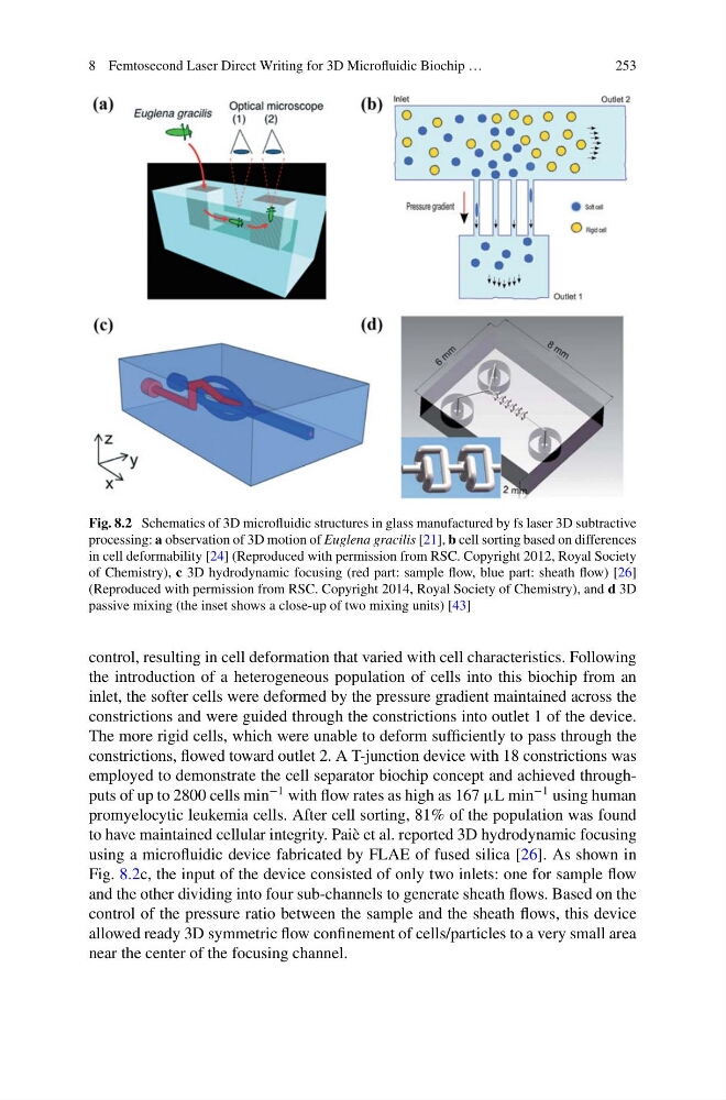
Fig. 8.2 Schematics of 3D microfluidic structures in glass manufactured by fs laser 3D subtractive
processing: a observation of 3D motion of Euglena gracilis [21], b cell sorting based on differences
in cell deformability [24] (Reproduced with permission from RSC. Copyright 2012, Royal Society
of Chemistry), c 3D hydrodynamic focusing (red part: sample flow, blue part: sheath flow) [26]
(Reproduced with permission from RSC. Copyright 2014, Royal Society of Chemistry), and d 3D
passive mixing (the inset shows a close-up of two mixing units) [43]
control, resulting in cell deformation that varied with cell characteristics. Following
the introduction of a heterogeneous population of cells into this biochip from an
inlet, the softer cells were deformed by the pressure gradient maintained across the
constrictions and were guided through the constrictions into outlet 1 of the device.
The more rigid cells, which were unable to deform sufficiently to pass through the
constrictions, flowed toward outlet 2. A T-junction device with 18 constrictions was
employed to demonstrate the cell separator biochip concept and achieved throughputs of up to 2800 cells min
−1 with flow rates as high as 167 µL min
−1 using human
promyelocytic leukemia cells. After cell sorting, 81% of the population was found
to have maintained cellular integrity. Paiè et al. reported 3D hydrodynamic focusing
using a microfluidic device fabricated by FLAE of fused silica [26]. As shown in
Fig. 8.2c, the input of the device consisted of only two inlets: one for sample flow
and the other dividing into four sub-channels to generate sheath flows. Based on the
control of the pressure ratio between the sample and the sheath flows, this device
allowed ready 3D symmetric flow confinement of cells/particles to a very small area
near the center of the focusing channel.
253
Fig. 8.2 Schematics of 3D microfluidic structures in glass manufactured by fs laser 3D subtractive
processing: a observation of 3D motion of Euglena gracilis [21], b cell sorting based on differences
in cell deformability [24] (Reproduced with permission from RSC. Copyright 2012, Royal Society
of Chemistry), c 3D hydrodynamic focusing (red part: sample flow, blue part: sheath flow) [26]
(Reproduced with permission from RSC. Copyright 2014, Royal Society of Chemistry), and d 3D
passive mixing (the inset shows a close-up of two mixing units) [43]
control, resulting in cell deformation that varied with cell characteristics. Following
the introduction of a heterogeneous population of cells into this biochip from an
inlet, the softer cells were deformed by the pressure gradient maintained across the
constrictions and were guided through the constrictions into outlet 1 of the device.
The more rigid cells, which were unable to deform sufficiently to pass through the
constrictions, flowed toward outlet 2. A T-junction device with 18 constrictions was
employed to demonstrate the cell separator biochip concept and achieved throughputs of up to 2800 cells min
−1 with flow rates as high as 167 µL min
−1 using human
promyelocytic leukemia cells. After cell sorting, 81% of the population was found
to have maintained cellular integrity. Paiè et al. reported 3D hydrodynamic focusing
using a microfluidic device fabricated by FLAE of fused silica [26]. As shown in
Fig. 8.2c, the input of the device consisted of only two inlets: one for sample flow
and the other dividing into four sub-channels to generate sheath flows. Based on the
control of the pressure ratio between the sample and the sheath flows, this device
allowed ready 3D symmetric flow confinement of cells/particles to a very small area
near the center of the focusing channel.