

80
6 Passive Droplet Routing
c 1
1
l
3
l
3
c
c 2
the non−default channel
l 2
Header blocks
the default channel
Sink
Flow
Payload will enter
Sink
1
c
Header blocks
the default channel
c
the non−default channel
3
c
2
Flow
Flow
Flow
Payload will enter
Bypass Channel
(a) Without bypass
(b) With bypass
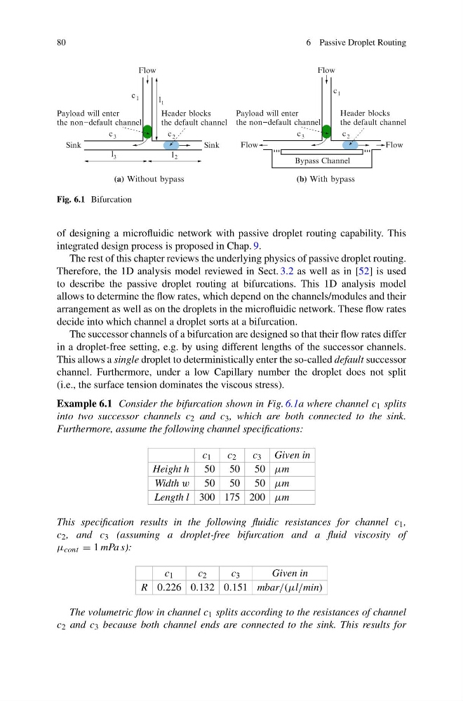
Fig. 6.1 Bifurcation
of designing a microfluidic network with passive droplet routing capability. This
integrated design process is proposed in Chap. 9.
The rest of this chapter reviews the underlying physics of passive droplet routing.
Therefore, the 1D analysis model reviewed in Sect. 3.2 as well as in [52] is used
to describe the passive droplet routing at bifurcations. This 1D analysis model
allows to determine the flow rates, which depend on the channels/modules and their
arrangement as well as on the droplets in the microfluidic network. These flow rates
decide into which channel a droplet sorts at a bifurcation.
The successor channels of a bifurcation are designed so that their flow rates differ
in a droplet-free setting, e.g. by using different lengths of the successor channels.
This allows a single droplet to deterministically enter the so-called default successor
channel. Furthermore, under a low Capillary number the droplet does not split
(i.e., the surface tension dominates the viscous stress).
Example 6.1 Consider the bifurcation shown in Fig. 6.1a where channel c 1 splits
into two successor channels c 2 and c 3 , which are both connected to the sink.
Furthermore, assume the following channel specifications:
c 1
c 2
c 3 Given in
Height h 50 50 50 μm
Width w 50 50 50 μm
Length l 300 175 200 μm
This specification results in the following fluidic resistances for channel c 1 ,
c 2 , and c 3 (assuming a droplet-free bifurcation and a fluid viscosity of
μ cont = 1 mPa s):
c 1
c 2
c 3
Given in
R 0.226 0.132 0.151 mbar/(μl/min)
The volumetric flow in channel c 1 splits according to the resistances of channel
c 2 and c 3 because both channel ends are connected to the sink. This results for
6 Passive Droplet Routing
c 1
1
l
3
l
3
c
c 2
the non−default channel
l 2
Header blocks
the default channel
Sink
Flow
Payload will enter
Sink
1
c
Header blocks
the default channel
c
the non−default channel
3
c
2
Flow
Flow
Flow
Payload will enter
Bypass Channel
(a) Without bypass
(b) With bypass
Fig. 6.1 Bifurcation
of designing a microfluidic network with passive droplet routing capability. This
integrated design process is proposed in Chap. 9.
The rest of this chapter reviews the underlying physics of passive droplet routing.
Therefore, the 1D analysis model reviewed in Sect. 3.2 as well as in [52] is used
to describe the passive droplet routing at bifurcations. This 1D analysis model
allows to determine the flow rates, which depend on the channels/modules and their
arrangement as well as on the droplets in the microfluidic network. These flow rates
decide into which channel a droplet sorts at a bifurcation.
The successor channels of a bifurcation are designed so that their flow rates differ
in a droplet-free setting, e.g. by using different lengths of the successor channels.
This allows a single droplet to deterministically enter the so-called default successor
channel. Furthermore, under a low Capillary number the droplet does not split
(i.e., the surface tension dominates the viscous stress).
Example 6.1 Consider the bifurcation shown in Fig. 6.1a where channel c 1 splits
into two successor channels c 2 and c 3 , which are both connected to the sink.
Furthermore, assume the following channel specifications:
c 1
c 2
c 3 Given in
Height h 50 50 50 μm
Width w 50 50 50 μm
Length l 300 175 200 μm
This specification results in the following fluidic resistances for channel c 1 ,
c 2 , and c 3 (assuming a droplet-free bifurcation and a fluid viscosity of
μ cont = 1 mPa s):
c 1
c 2
c 3
Given in
R 0.226 0.132 0.151 mbar/(μl/min)
The volumetric flow in channel c 1 splits according to the resistances of channel
c 2 and c 3 because both channel ends are connected to the sink. This results for