

54
4 Dimensioning Droplet Microfluidic Networks
This viscosity in combination with the specification of the selected modules
allows to determine their resistances (given in mbar/(μl/min)) 1 :
R sorter R m 1 , R h 1 , R t 1 , R d 1
0.07
0.35
Now, let’s assume that the designer (e.g., based on his/her experience or on
a purely trial-and-error basis) dimensions all remaining channels with the same
dimensions, i.e. a width of w = 50 μm, a height of h = 50 μm, and a length of
l = 200 μm. This allows to determine the resistance of these channels using Eq. 3.2
(given in mbar/(μl/min)):
R c 1 , R c 2 , R c 3 , R c 4 , R c 5 , R c 6 , R c 7 , R c 8 , R c 9 , R c 10 , R c 11
0.15
Conducting the steps illustrated in the example would usually complete the
specification. However, as discussed above, the chosen dimensions of the channels
may yield a specification that does not work as intended. Thus far, designers had
the choice to simulate their specification (using the method presented in Chap. 3
and [52]) and to manually inspect if any of the problems discussed above occurs.
But here, a method is provided which is capable of automatically validating the
specification.
First let’s consider the problem where droplets flow in the opposite direction:
• Objective 1—A droplet flows in the opposite direction: This is the case when
at least one channel/module exists in which its determined flow rate Q c /Q m is
negative.
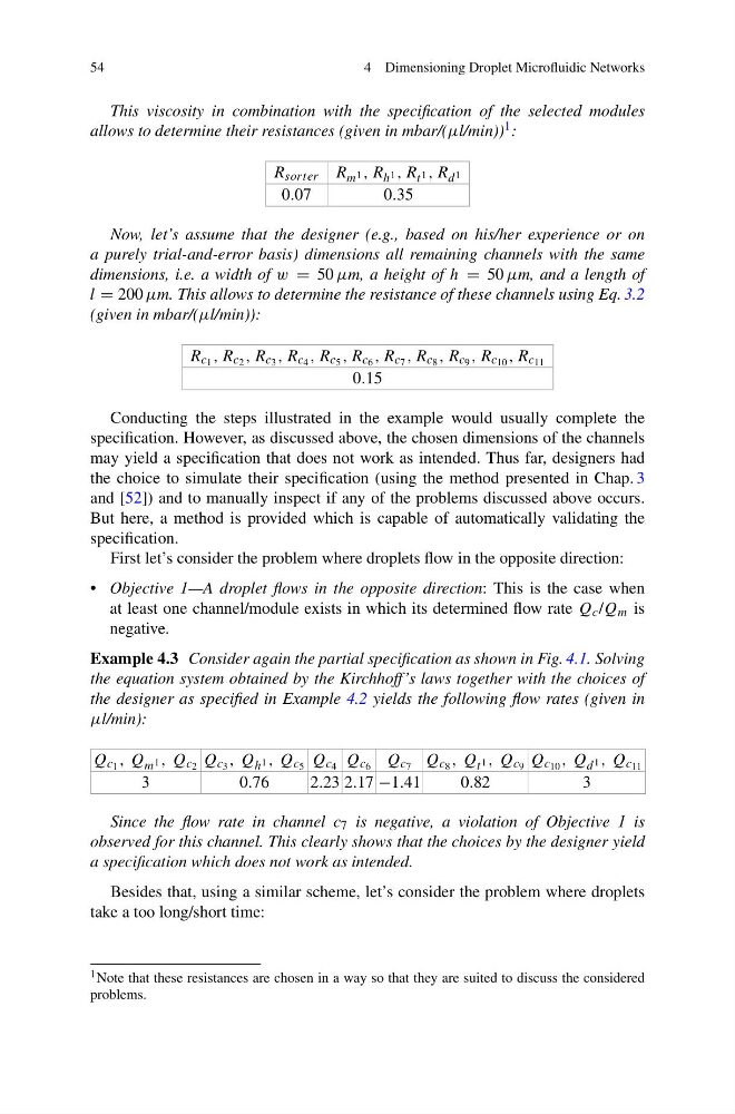
Example 4.3 Consider again the partial specification as shown in Fig. 4.1. Solving
the equation system obtained by the Kirchhoff’s laws together with the choices of
the designer as specified in Example 4.2 yields the following flow rates (given in
μl/min):
Q c 1 , Q m 1 , Q c 2 Q c 3 , Q h 1 , Q c 5 Q c 4 Q c 6 Q c 7 Q c 8 , Q t 1 , Q c 9 Q c 10 , Q d 1 , Q c 11
3
0.76
2.23 2.17 −1.41
0.82
3
Since the flow rate in channel c 7 is negative, a violation of Objective 1 is
observed for this channel. This clearly shows that the choices by the designer yield
a specification which does not work as intended.
Besides that, using a similar scheme, let’s consider the problem where droplets
take a too long/short time:
1 Note that these resistances are chosen in a way so that they are suited to discuss the considered
problems.
4 Dimensioning Droplet Microfluidic Networks
This viscosity in combination with the specification of the selected modules
allows to determine their resistances (given in mbar/(μl/min)) 1 :
R sorter R m 1 , R h 1 , R t 1 , R d 1
0.07
0.35
Now, let’s assume that the designer (e.g., based on his/her experience or on
a purely trial-and-error basis) dimensions all remaining channels with the same
dimensions, i.e. a width of w = 50 μm, a height of h = 50 μm, and a length of
l = 200 μm. This allows to determine the resistance of these channels using Eq. 3.2
(given in mbar/(μl/min)):
R c 1 , R c 2 , R c 3 , R c 4 , R c 5 , R c 6 , R c 7 , R c 8 , R c 9 , R c 10 , R c 11
0.15
Conducting the steps illustrated in the example would usually complete the
specification. However, as discussed above, the chosen dimensions of the channels
may yield a specification that does not work as intended. Thus far, designers had
the choice to simulate their specification (using the method presented in Chap. 3
and [52]) and to manually inspect if any of the problems discussed above occurs.
But here, a method is provided which is capable of automatically validating the
specification.
First let’s consider the problem where droplets flow in the opposite direction:
• Objective 1—A droplet flows in the opposite direction: This is the case when
at least one channel/module exists in which its determined flow rate Q c /Q m is
negative.
Example 4.3 Consider again the partial specification as shown in Fig. 4.1. Solving
the equation system obtained by the Kirchhoff’s laws together with the choices of
the designer as specified in Example 4.2 yields the following flow rates (given in
μl/min):
Q c 1 , Q m 1 , Q c 2 Q c 3 , Q h 1 , Q c 5 Q c 4 Q c 6 Q c 7 Q c 8 , Q t 1 , Q c 9 Q c 10 , Q d 1 , Q c 11
3
0.76
2.23 2.17 −1.41
0.82
3
Since the flow rate in channel c 7 is negative, a violation of Objective 1 is
observed for this channel. This clearly shows that the choices by the designer yield
a specification which does not work as intended.
Besides that, using a similar scheme, let’s consider the problem where droplets
take a too long/short time:
1 Note that these resistances are chosen in a way so that they are suited to discuss the considered
problems.