

3.4 Case Study
39
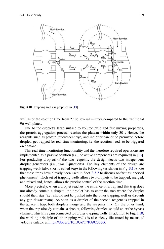
Fig. 3.10 Trapping wells as proposed in [13]
well as of the reaction time from 2 h to several minutes compared to the traditional
96-well plates.
Due to the droplet’s large surface to volume ratio and fast mixing properties,
the protein aggregation process reaches the plateau within only 30 s. Hence, the
reagents such as protein, fluorescent dye, and inhibitor cannot be premixed before
droplets get trapped for real-time monitoring, i.e. the reaction needs to be triggered
on demand.
This real-time monitoring functionality and the therefore required operations are
implemented as a passive solution (i.e., no active components are required) in [13].
For producing droplets of the two reagents, the design needs two independent
droplet generators (i.e., two T-junctions). The key elements of the design are
trapping wells (also shortly called traps in the following) as shown in Fig. 3.10 (note
that these traps have already been used in Sect. 3.3.2 to discuss so-far unsupported
phenomena). Each set of trapping wells allows two droplets to be trapped, merged,
and mixed and, hence, allows the precise control of the reaction time.
More precisely, when a droplet reaches the entrance of a trap and this trap does
not already contain a droplet, the droplet has to enter the trap where the droplet
should then stay (i.e., should not be pushed into the other trapping well or through
any gap downstream). As soon as a droplet of the second reagent is trapped in
the adjacent trap, both droplets merge and the reagents mix. On the other hand,
when the trap already contains a droplet, following droplets should enter the bypass
channel, which is again connected to further trapping wells. In addition to Fig. 3.10,
the working principle of the trapping wells is also nicely illustrated by means of
videos available at https://doi.org/10.1039/C7RA02336G.
39
Fig. 3.10 Trapping wells as proposed in [13]
well as of the reaction time from 2 h to several minutes compared to the traditional
96-well plates.
Due to the droplet’s large surface to volume ratio and fast mixing properties,
the protein aggregation process reaches the plateau within only 30 s. Hence, the
reagents such as protein, fluorescent dye, and inhibitor cannot be premixed before
droplets get trapped for real-time monitoring, i.e. the reaction needs to be triggered
on demand.
This real-time monitoring functionality and the therefore required operations are
implemented as a passive solution (i.e., no active components are required) in [13].
For producing droplets of the two reagents, the design needs two independent
droplet generators (i.e., two T-junctions). The key elements of the design are
trapping wells (also shortly called traps in the following) as shown in Fig. 3.10 (note
that these traps have already been used in Sect. 3.3.2 to discuss so-far unsupported
phenomena). Each set of trapping wells allows two droplets to be trapped, merged,
and mixed and, hence, allows the precise control of the reaction time.
More precisely, when a droplet reaches the entrance of a trap and this trap does
not already contain a droplet, the droplet has to enter the trap where the droplet
should then stay (i.e., should not be pushed into the other trapping well or through
any gap downstream). As soon as a droplet of the second reagent is trapped in
the adjacent trap, both droplets merge and the reagents mix. On the other hand,
when the trap already contains a droplet, following droplets should enter the bypass
channel, which is again connected to further trapping wells. In addition to Fig. 3.10,
the working principle of the trapping wells is also nicely illustrated by means of
videos available at https://doi.org/10.1039/C7RA02336G.