

2.2 Droplet Microfluidic Networks
15
2.2 Droplet Microfluidic Networks
Droplet microfluidics is a fast evolving field [68], which is confirmed by the
numerous studies reported over the past decade as summarized by a number
of review articles [16, 69, 104, 107, 117]. Fundamental studies mainly focus on
investigating and elucidating two-phase flow and transport phenomena as well
as exploring functionalities for droplet manipulation [2, 14, 15, 20, 38, 39, 98],
while application driven studies aim to exploit droplet microfluidics to address
the challenges associated with the current best practices [9, 12, 19, 22, 77, 92].
Both active and passive modules have been developed for manipulating droplets
such as droplet generation, merging, splitting, and trapping. Active modules utilize,
e.g., valves or electric fields to manipulate droplets, while passive methods rely on
the variation of applied pressures, geometries, and fluid properties to manipulate
droplets and thus do not need external components to be integrated with microfluidic devices. More details on modules and their implementations can be found,
e.g., in [55, 75, 76, 81, 114, 115, 117, 124].
In the following, the structure of droplet microfluidics and especially of resulting
networks is described. Finally, this section briefly reviews commonly used fabrication settings.
A droplet microfluidic network consists of multiple paths through which the
droplets can flow. Through these paths, multiple and parallel experiments can
be realized on a single device [32], which increases the device’s flexibility,
effectiveness, as well as reusability. By splitting a microfluidic channel into two or
more successor channels (these splits are called bifurcations or junctions), different
paths through the network can be realized. Similarly, by merging two or more
channels into one channel, paths are combined. Along the paths of a microfluidic
network different operations on the droplets can be executed and, hence, different
experiments can be conducted.
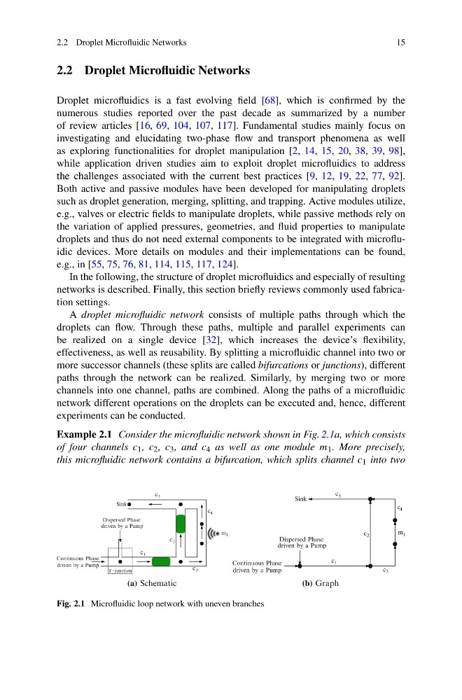
Example 2.1 Consider the microfluidic network shown in Fig. 2.1a, which consists
of four channels c 1 , c 2 , c 3 , and c 4 as well as one module m 1 . More precisely,
this microfluidic network contains a bifurcation, which splits channel c 1 into two
2
c
3
c
4
c
5
c
1
c 1
Sink
driven by a Pump
Continuous Phase
driven by a Pump
Dispersed Phase
T−junction
m
Dispersed Phase
c
2
c
1
m
4
c
5
c
3
c
Sink
Continuous Phase
driven by a Pump
driven by a Pump
1
(a) Schematic
(b) Graph
Fig. 2.1 Microfluidic loop network with uneven branches
15
2.2 Droplet Microfluidic Networks
Droplet microfluidics is a fast evolving field [68], which is confirmed by the
numerous studies reported over the past decade as summarized by a number
of review articles [16, 69, 104, 107, 117]. Fundamental studies mainly focus on
investigating and elucidating two-phase flow and transport phenomena as well
as exploring functionalities for droplet manipulation [2, 14, 15, 20, 38, 39, 98],
while application driven studies aim to exploit droplet microfluidics to address
the challenges associated with the current best practices [9, 12, 19, 22, 77, 92].
Both active and passive modules have been developed for manipulating droplets
such as droplet generation, merging, splitting, and trapping. Active modules utilize,
e.g., valves or electric fields to manipulate droplets, while passive methods rely on
the variation of applied pressures, geometries, and fluid properties to manipulate
droplets and thus do not need external components to be integrated with microfluidic devices. More details on modules and their implementations can be found,
e.g., in [55, 75, 76, 81, 114, 115, 117, 124].
In the following, the structure of droplet microfluidics and especially of resulting
networks is described. Finally, this section briefly reviews commonly used fabrication settings.
A droplet microfluidic network consists of multiple paths through which the
droplets can flow. Through these paths, multiple and parallel experiments can
be realized on a single device [32], which increases the device’s flexibility,
effectiveness, as well as reusability. By splitting a microfluidic channel into two or
more successor channels (these splits are called bifurcations or junctions), different
paths through the network can be realized. Similarly, by merging two or more
channels into one channel, paths are combined. Along the paths of a microfluidic
network different operations on the droplets can be executed and, hence, different
experiments can be conducted.
Example 2.1 Consider the microfluidic network shown in Fig. 2.1a, which consists
of four channels c 1 , c 2 , c 3 , and c 4 as well as one module m 1 . More precisely,
this microfluidic network contains a bifurcation, which splits channel c 1 into two
2
c
3
c
4
c
5
c
1
c 1
Sink
driven by a Pump
Continuous Phase
driven by a Pump
Dispersed Phase
T−junction
m
Dispersed Phase
c
2
c
1
m
4
c
5
c
3
c
Sink
Continuous Phase
driven by a Pump
driven by a Pump
1
(a) Schematic
(b) Graph
Fig. 2.1 Microfluidic loop network with uneven branches