

120
8 Generating Droplet Sequences
Symbolic Formulation of the Droplet Sequence and Droplet Positions
A droplet sequence is represented by two bit vectors. One bit vector represents the
injection of the payload droplet and the other represents the injection of header
droplets. Both vectors are of length T up . More formally:
Definition 8.3 Let inj P be the vector of length T up representing the injection of
the payload droplet. Further, let inj H be the vector of length T up representing the
injection of the header droplets. The left-most bit represents t = 1 in the notation.
Therefore, a 1 at position t in these bit vectors (i.e. inj P [t] = 1 or inj H [t] = 1)
represents the injection of a payload/header droplet in time step t. The time step in
which the payload is injected is given by the upper bound, i.e. the payload is injected
in time step T maxP ath . Therefore, the vector inj P contains a 1 at position T maxP ath
(i.e., inj P [T maxP ath ] = 1).
In addition to the droplet sequences, a formulation is needed which symbolically
represents the state (i.e., the droplet positions) of a microfluidic network at every
time step. As discussed above, there cannot be a droplet sequence longer than T up
time steps. Additionally, considering the maximal time steps that the latest possible
injected droplet needs to flow back to the MPU (given by the longest path), T up +
T maxP ath time steps have to be considered. In all those time steps droplets must not
coalesce.
Therefore, for all modules and channels and each time step 0 ≤ t ≤ T up +
T maxP ath , two bit vectors representing the header droplets and the payload droplet
are introduced, respectively. The lengths of the payload (header) bit vectors are
defined by the function pStep (hSteps)—cf. Sect. 8.1.1. A symbolic one-hot
encoding is applied to these bit vectors, where a 1 represents the presence of a
payload (header) droplet within a channel or module. When a payload (header)
droplet enters an entity (i.e., channel or module), the leftmost bit of the payload
(header) bit vector is assigned 1. Then, the positions of the 1 in the vector represent
how long droplets are already in the entity. More formally:
Definition 8.4 For each entity e ∈ C ∪ M and each discrete time step 0 ≤ t ≤
T up + T maxP ath , a bit vector for the payload droplet pd e,t and a bit vector for the
header droplets hd e,t are introduced. The lengths of the bit vectors pd e,t are defined
by pSteps(e) and the lengths of the bit vectors hd e,t are defined by hSteps(e).
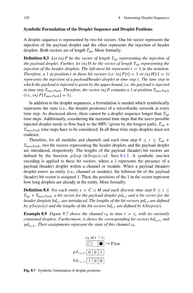
Example 8.9 Figure 8.7 shows the channel c 6 in time t = t x with its currently
contained droplets. Furthermore, it shows the corresponding bit vectors hd c 6 ,t x and
pd c 6 ,t x . Their assignments represent the state of this channel c 6 .
c 6 at t = t x
0 0 1
1 0 0
pd c 6 , t x
hd c 6 , t x
Flow
Fig. 8.7 Symbolic formulation of droplet positions
8 Generating Droplet Sequences
Symbolic Formulation of the Droplet Sequence and Droplet Positions
A droplet sequence is represented by two bit vectors. One bit vector represents the
injection of the payload droplet and the other represents the injection of header
droplets. Both vectors are of length T up . More formally:
Definition 8.3 Let inj P be the vector of length T up representing the injection of
the payload droplet. Further, let inj H be the vector of length T up representing the
injection of the header droplets. The left-most bit represents t = 1 in the notation.
Therefore, a 1 at position t in these bit vectors (i.e. inj P [t] = 1 or inj H [t] = 1)
represents the injection of a payload/header droplet in time step t. The time step in
which the payload is injected is given by the upper bound, i.e. the payload is injected
in time step T maxP ath . Therefore, the vector inj P contains a 1 at position T maxP ath
(i.e., inj P [T maxP ath ] = 1).
In addition to the droplet sequences, a formulation is needed which symbolically
represents the state (i.e., the droplet positions) of a microfluidic network at every
time step. As discussed above, there cannot be a droplet sequence longer than T up
time steps. Additionally, considering the maximal time steps that the latest possible
injected droplet needs to flow back to the MPU (given by the longest path), T up +
T maxP ath time steps have to be considered. In all those time steps droplets must not
coalesce.
Therefore, for all modules and channels and each time step 0 ≤ t ≤ T up +
T maxP ath , two bit vectors representing the header droplets and the payload droplet
are introduced, respectively. The lengths of the payload (header) bit vectors are
defined by the function pStep (hSteps)—cf. Sect. 8.1.1. A symbolic one-hot
encoding is applied to these bit vectors, where a 1 represents the presence of a
payload (header) droplet within a channel or module. When a payload (header)
droplet enters an entity (i.e., channel or module), the leftmost bit of the payload
(header) bit vector is assigned 1. Then, the positions of the 1 in the vector represent
how long droplets are already in the entity. More formally:
Definition 8.4 For each entity e ∈ C ∪ M and each discrete time step 0 ≤ t ≤
T up + T maxP ath , a bit vector for the payload droplet pd e,t and a bit vector for the
header droplets hd e,t are introduced. The lengths of the bit vectors pd e,t are defined
by pSteps(e) and the lengths of the bit vectors hd e,t are defined by hSteps(e).
Example 8.9 Figure 8.7 shows the channel c 6 in time t = t x with its currently
contained droplets. Furthermore, it shows the corresponding bit vectors hd c 6 ,t x and
pd c 6 ,t x . Their assignments represent the state of this channel c 6 .
c 6 at t = t x
0 0 1
1 0 0
pd c 6 , t x
hd c 6 , t x
Flow
Fig. 8.7 Symbolic formulation of droplet positions