

116
8 Generating Droplet Sequences
validation, it is guaranteed that all interdependencies between droplets are considered and, hence, the obtained results are indeed suitable.
8.3 Verification
The method proposed in the previous section only considers promising candidates of
droplet sequences. That means, this method cannot guarantee to determine a droplet
sequence or cannot prove that no droplet sequence exists which would realize an
experiment at least on the discrete model.
This section presents an automatic method for verifying whether a given
microfluidic network allows to correctly route the droplets on the discrete model.
Therefore, a microfluidic network is considered only valid on the discrete model, if
it allows to execute all experiments defined in the set of experiments . However,
verifying a microfluidic network whether it allows to execute all desired experiments
is a nontrivial task. The following example shows an attempt for determining a
droplet sequence on the before introduced discrete model.
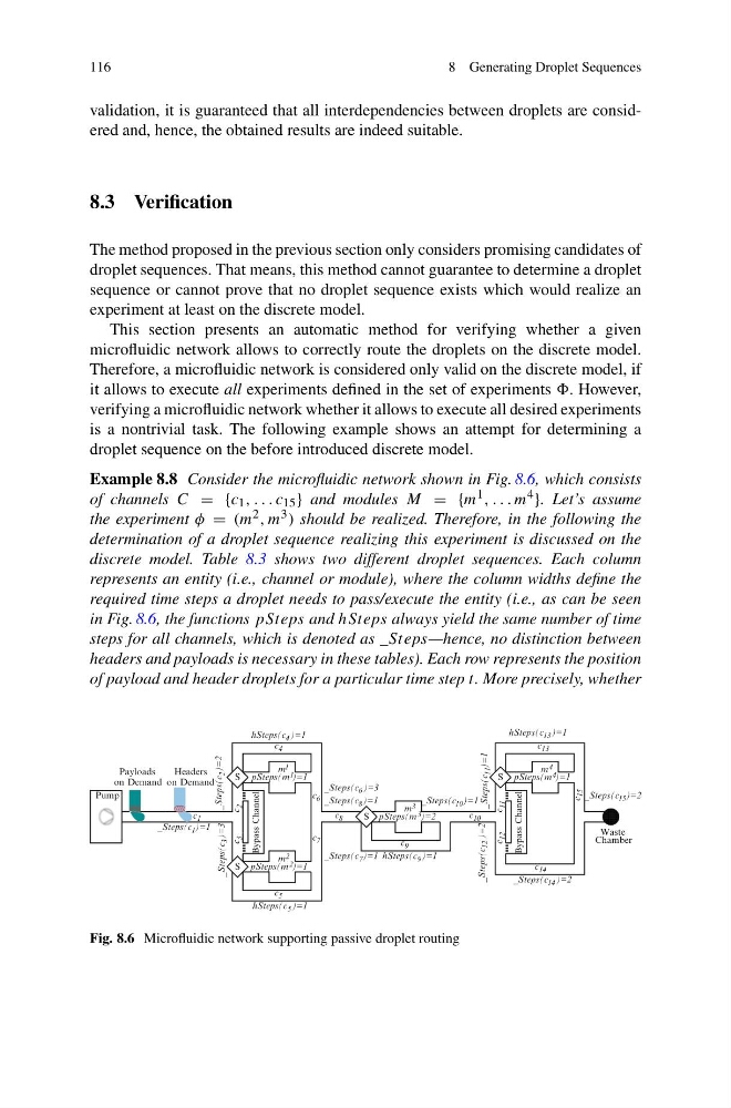
Example 8.8 Consider the microfluidic network shown in Fig. 8.6, which consists
of channels C = {c 1 , . . . c 15 } and modules M = {m 1 , . . . m 4 }. Let’s assume
the experiment φ = (m 2 , m 3 ) should be realized. Therefore, in the following the
determination of a droplet sequence realizing this experiment is discussed on the
discrete model. Table 8.3 shows two different droplet sequences. Each column
represents an entity (i.e., channel or module), where the column widths define the
required time steps a droplet needs to pass/execute the entity (i.e., as can be seen
in Fig. 8.6, the functions pSteps and hSteps always yield the same number of time
steps for all channels, which is denoted as _Steps—hence, no distinction between
headers and payloads is necessary in these tables). Each row represents the position
of payload and header droplets for a particular time step t. More precisely, whether
)=2
c
2
c
12
c
11
c
5
c
6
c
7
c
8
c
9
c
10
c
13
c
15
c
14
c
4
c
m 1
m 2
m 3
m 4
hSteps(c 5 )=1
)=1
3
on Demand
Bypass Channel
S
S
S
Bypass Channel
S
Waste
Chamber
on Demand
Payloads
Headers
Pump
1
4
hSteps(c 9
hSteps(c 13
c 1
_Steps(c )=1
)=3
_Steps(c
3
_Steps(c
2 )=2
hSteps(c )=1
pSteps(m 2 )=1
pSteps(m 1 )=1
pSteps(m )=2
3
_Steps(c 7 )=1
_Steps(c 10
_Steps(c
11 )=1
_Steps(c 14
_Steps(c 15
pSteps(m 4 )=1
)=1
_Steps(c 8
_Steps(c )=3
6
)=1
)=2
_Steps(c
12 )=2
)=1
Fig. 8.6 Microfluidic network supporting passive droplet routing
8 Generating Droplet Sequences
validation, it is guaranteed that all interdependencies between droplets are considered and, hence, the obtained results are indeed suitable.
8.3 Verification
The method proposed in the previous section only considers promising candidates of
droplet sequences. That means, this method cannot guarantee to determine a droplet
sequence or cannot prove that no droplet sequence exists which would realize an
experiment at least on the discrete model.
This section presents an automatic method for verifying whether a given
microfluidic network allows to correctly route the droplets on the discrete model.
Therefore, a microfluidic network is considered only valid on the discrete model, if
it allows to execute all experiments defined in the set of experiments . However,
verifying a microfluidic network whether it allows to execute all desired experiments
is a nontrivial task. The following example shows an attempt for determining a
droplet sequence on the before introduced discrete model.
Example 8.8 Consider the microfluidic network shown in Fig. 8.6, which consists
of channels C = {c 1 , . . . c 15 } and modules M = {m 1 , . . . m 4 }. Let’s assume
the experiment φ = (m 2 , m 3 ) should be realized. Therefore, in the following the
determination of a droplet sequence realizing this experiment is discussed on the
discrete model. Table 8.3 shows two different droplet sequences. Each column
represents an entity (i.e., channel or module), where the column widths define the
required time steps a droplet needs to pass/execute the entity (i.e., as can be seen
in Fig. 8.6, the functions pSteps and hSteps always yield the same number of time
steps for all channels, which is denoted as _Steps—hence, no distinction between
headers and payloads is necessary in these tables). Each row represents the position
of payload and header droplets for a particular time step t. More precisely, whether
)=2
c
2
c
12
c
11
c
5
c
6
c
7
c
8
c
9
c
10
c
13
c
15
c
14
c
4
c
m 1
m 2
m 3
m 4
hSteps(c 5 )=1
)=1
3
on Demand
Bypass Channel
S
S
S
Bypass Channel
S
Waste
Chamber
on Demand
Payloads
Headers
Pump
1
4
hSteps(c 9
hSteps(c 13
c 1
_Steps(c )=1
)=3
_Steps(c
3
_Steps(c
2 )=2
hSteps(c )=1
pSteps(m 2 )=1
pSteps(m 1 )=1
pSteps(m )=2
3
_Steps(c 7 )=1
_Steps(c 10
_Steps(c
11 )=1
_Steps(c 14
_Steps(c 15
pSteps(m 4 )=1
)=1
_Steps(c 8
_Steps(c )=3
6
)=1
)=2
_Steps(c
12 )=2
)=1
Fig. 8.6 Microfluidic network supporting passive droplet routing