

102
8 Generating Droplet Sequences
Constraints to Avoid Coalescences of Droplets: Unintended coalescences of
droplets are avoided by restricting the distance of two droplets to a minimum
value. In the discrete model, this is abstracted to the corresponding number of
time steps T a droplet would need to pass this distance. Therefore, all droplets
represented in the model must have a distance of at least T time steps.
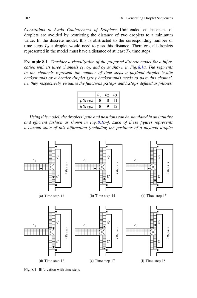
Example 8.1 Consider a visualization of the proposed discrete model for a bifurcation with its three channels c 1 , c 2 , and c 3 as shown in Fig. 8.1a. The segments
in the channels represent the number of time steps a payload droplet (white
background) or a header droplet (gray background) needs to pass this channel,
i.e. they, respectively, visualize the functions pSteps and hSteps defined as follows:
c 1 c 2 c 3
pSteps 8 8 11
hSteps 8 9 12
Using this model, the droplets’ path and positions can be simulated in an intuitive
and efficient fashion as shown in Fig. 8.1a–f. Each of these figures represents
a current state of this bifurcation (including the positions of a payload droplet
c 1
c 3
c 2
c
By p ass
c 1
c 3
c 2
c
By p ass
(b) Time step 14
c 1
c 3
c 2
c
By p ass
(c) Time step 15
c 1
c 3
c 2
c
By p ass
(d) Time step 16
c 1
c 3
c 2
c
By p ass
(e) Time step 17
c 1
c 3
c 2
c
By p ass
(f) Time step 18
(a) Time step 13
Fig. 8.1 Bifurcation with time steps
8 Generating Droplet Sequences
Constraints to Avoid Coalescences of Droplets: Unintended coalescences of
droplets are avoided by restricting the distance of two droplets to a minimum
value. In the discrete model, this is abstracted to the corresponding number of
time steps T a droplet would need to pass this distance. Therefore, all droplets
represented in the model must have a distance of at least T time steps.
Example 8.1 Consider a visualization of the proposed discrete model for a bifurcation with its three channels c 1 , c 2 , and c 3 as shown in Fig. 8.1a. The segments
in the channels represent the number of time steps a payload droplet (white
background) or a header droplet (gray background) needs to pass this channel,
i.e. they, respectively, visualize the functions pSteps and hSteps defined as follows:
c 1 c 2 c 3
pSteps 8 8 11
hSteps 8 9 12
Using this model, the droplets’ path and positions can be simulated in an intuitive
and efficient fashion as shown in Fig. 8.1a–f. Each of these figures represents
a current state of this bifurcation (including the positions of a payload droplet
c 1
c 3
c 2
c
By p ass
c 1
c 3
c 2
c
By p ass
(b) Time step 14
c 1
c 3
c 2
c
By p ass
(c) Time step 15
c 1
c 3
c 2
c
By p ass
(d) Time step 16
c 1
c 3
c 2
c
By p ass
(e) Time step 17
c 1
c 3
c 2
c
By p ass
(f) Time step 18
(a) Time step 13
Fig. 8.1 Bifurcation with time steps