

20 Tachyons and Causality
225
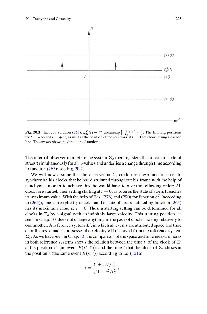
Fig. 20.2 Tachyon solution (265), q T
∞ (t) =
2a
π arctan exp
−π co
Lo t
+
a
2 . The limiting positions
for t = −∞ and t = +∞, as well as the position of the solutions at t = 0 are shown using a dashed
line. The arrows show the direction of motion
The internal observer in a reference system o then registers that a certain state of
stress t simultaneously for all x-values and underlies a change through time according
to function (265); see Fig. 20.2.
We will now assume that the observer in o could use these facts in order to
synchronise his clocks that he has distributed throughout his frame with the help of
a tachyon. In order to achieve this, he would have to give the following order: All
clocks are started, their setting starting at t = 0, as soon as the state of stress t reaches
its maximum value. With the help of Eqs. (276) and (290) for function q
T (according
to (265)), one can explicitly check that the state of stress defined by function (265)
has its maximum value at t = 0. Thus, a starting setting can be determined for all
clocks in o by a signal with an infinitely large velocity. This starting position, as
seen in Chap. 10, does not change anything in the pace of clocks moving relatively to
one another. A reference system
, in which all events are attributed space and time
coordinates x
and t
, possesses the velocity v if observed from the reference system
o . As we have seen in Chap. 13, the comparison of the space and time measurements
in both reference systems shows the relation between the time t
of the clock of
at the position x
an event E(x
, t
)
, and the time t that the clock of o shows at
the position x (the same event E(x, t)) according to Eq. (151a),
t =
t
+ v x
/c
2
o
1 − v 2 /c 2
o
,
225
Fig. 20.2 Tachyon solution (265), q T
∞ (t) =
2a
π arctan exp
−π co
Lo t
+
a
2 . The limiting positions
for t = −∞ and t = +∞, as well as the position of the solutions at t = 0 are shown using a dashed
line. The arrows show the direction of motion
The internal observer in a reference system o then registers that a certain state of
stress t simultaneously for all x-values and underlies a change through time according
to function (265); see Fig. 20.2.
We will now assume that the observer in o could use these facts in order to
synchronise his clocks that he has distributed throughout his frame with the help of
a tachyon. In order to achieve this, he would have to give the following order: All
clocks are started, their setting starting at t = 0, as soon as the state of stress t reaches
its maximum value. With the help of Eqs. (276) and (290) for function q
T (according
to (265)), one can explicitly check that the state of stress defined by function (265)
has its maximum value at t = 0. Thus, a starting setting can be determined for all
clocks in o by a signal with an infinitely large velocity. This starting position, as
seen in Chap. 10, does not change anything in the pace of clocks moving relatively to
one another. A reference system
, in which all events are attributed space and time
coordinates x
and t
, possesses the velocity v if observed from the reference system
o . As we have seen in Chap. 13, the comparison of the space and time measurements
in both reference systems shows the relation between the time t
of the clock of
at the position x
an event E(x
, t
)
, and the time t that the clock of o shows at
the position x (the same event E(x, t)) according to Eq. (151a),
t =
t
+ v x
/c
2
o
1 − v 2 /c 2
o
,