

63
Fundamentals of Electrochemical Double-Layer Supercapacitors
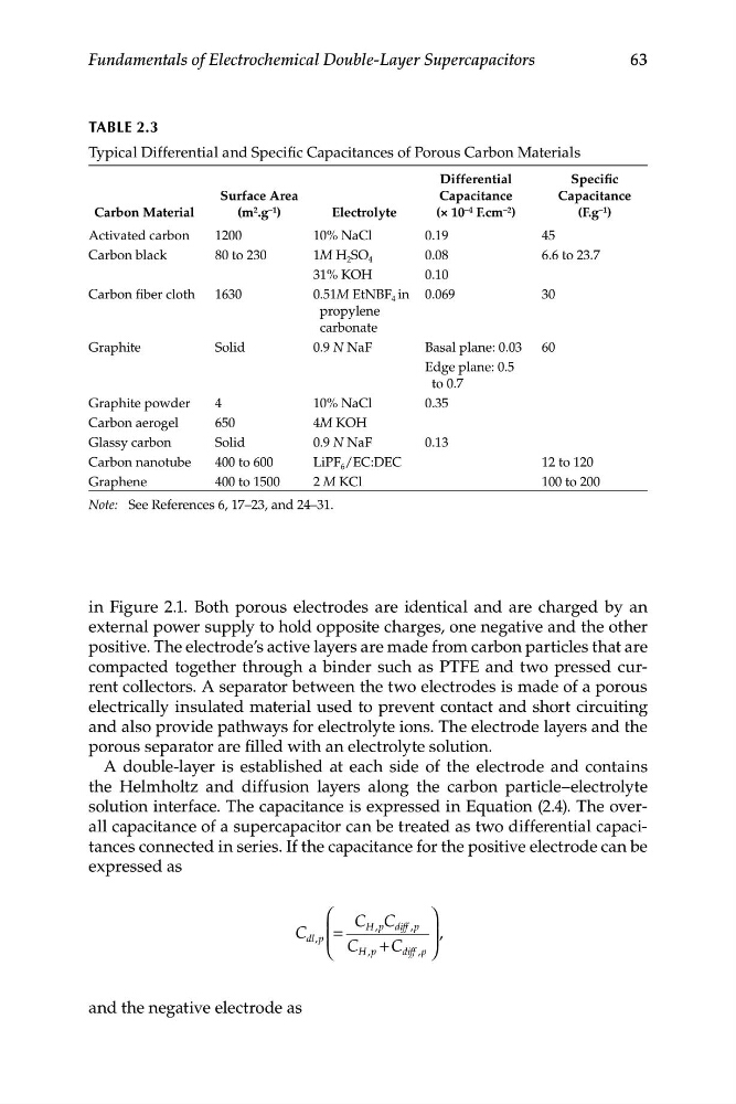
TABLE 2.3
Typical Differential and Specific Capacitances of Porous Carbon Materials
Differential
Specific
Surface Area
Capacitance
Capacitance
Carbon Material
(m 2 .g –1 )
Electrolyte
(× 10 –4 F.cm –2 )
(F.g –1 )
Activated carbon
1200
10% NaCl
0.19
45
Carbon black
80 to 230
1M H 2 SO 4
0.08
6.6 to 23.7
31% KOH
0.10
Carbon fiber cloth
1630
0.51M EtNBF 4 in 0.069
30
propylene
carbonate
Graphite
Solid
0.9 N NaF
Basal plane: 0.03 60
Edge plane: 0.5
to 0.7
Graphite powder
4
10% NaCl
0.35
Carbon aerogel
650
4M KOH
Glassy carbon
Solid
0.9 N NaF
0.13
Carbon nanotube
400 to 600
LiPF 6 /EC:DEC
12 to 120
Graphene
400 to 1500
2 M KCl
100 to 200
Note: See References 6, 17–23, and 24–31.
in Figure 2.1. Both porous electrodes are identical and are charged by an
external power supply to hold opposite charges, one negative and the other
positive. The electrode’s active layers are made from carbon particles that are
compacted together through a binder such as PTFE and two pressed current collectors. A separator between the two electrodes is made of a porous
electrically insulated material used to prevent contact and short circuiting
and also provide pathways for electrolyte ions. The electrode layers and the
porous separator are filled with an electrolyte solution.
A double-layer is established at each side of the electrode and contains
the Helmholtz and diffusion layers along the carbon particle–electrolyte
solution interface. The capacitance is expressed in Equation (2.4). The overall capacitance of a supercapacitor can be treated as two differential capacitances connected in series. If the capacitance for the positive electrode can be
expressed as
⎛
⎞
H p
,
diff p
,
C dl p ⎜ ⎜ =
C C
⎟ ⎟ ,
,
C + C
⎝
H p
,
diff p
, ⎠
and the negative electrode as
Fundamentals of Electrochemical Double-Layer Supercapacitors
TABLE 2.3
Typical Differential and Specific Capacitances of Porous Carbon Materials
Differential
Specific
Surface Area
Capacitance
Capacitance
Carbon Material
(m 2 .g –1 )
Electrolyte
(× 10 –4 F.cm –2 )
(F.g –1 )
Activated carbon
1200
10% NaCl
0.19
45
Carbon black
80 to 230
1M H 2 SO 4
0.08
6.6 to 23.7
31% KOH
0.10
Carbon fiber cloth
1630
0.51M EtNBF 4 in 0.069
30
propylene
carbonate
Graphite
Solid
0.9 N NaF
Basal plane: 0.03 60
Edge plane: 0.5
to 0.7
Graphite powder
4
10% NaCl
0.35
Carbon aerogel
650
4M KOH
Glassy carbon
Solid
0.9 N NaF
0.13
Carbon nanotube
400 to 600
LiPF 6 /EC:DEC
12 to 120
Graphene
400 to 1500
2 M KCl
100 to 200
Note: See References 6, 17–23, and 24–31.
in Figure 2.1. Both porous electrodes are identical and are charged by an
external power supply to hold opposite charges, one negative and the other
positive. The electrode’s active layers are made from carbon particles that are
compacted together through a binder such as PTFE and two pressed current collectors. A separator between the two electrodes is made of a porous
electrically insulated material used to prevent contact and short circuiting
and also provide pathways for electrolyte ions. The electrode layers and the
porous separator are filled with an electrolyte solution.
A double-layer is established at each side of the electrode and contains
the Helmholtz and diffusion layers along the carbon particle–electrolyte
solution interface. The capacitance is expressed in Equation (2.4). The overall capacitance of a supercapacitor can be treated as two differential capacitances connected in series. If the capacitance for the positive electrode can be
expressed as
⎛
⎞
H p
,
diff p
,
C dl p ⎜ ⎜ =
C C
⎟ ⎟ ,
,
C + C
⎝
H p
,
diff p
, ⎠
and the negative electrode as