

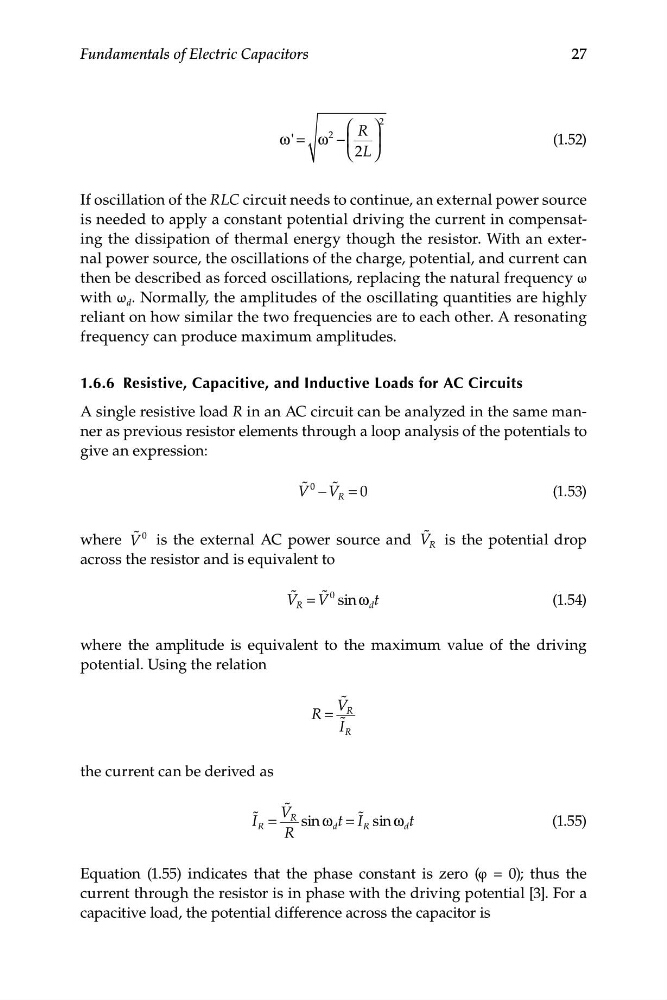
27
Fundamentals of Electric Capacitors
'
2
⎛ R ⎞
2
ω = ω − ⎜ ⎟
(1.52)
⎝ 2L ⎠
If oscillation of the RLC circuit needs to continue, an external power source
is needed to apply a constant potential driving the current in compensating the dissipation of thermal energy though the resistor. With an external power source, the oscillations of the charge, potential, and current can
then be described as forced oscillations, replacing the natural frequency ω
with ω d . Normally, the amplitudes of the oscillating quantities are highly
reliant on how similar the two frequencies are to each other. A resonating
frequency can produce maximum amplitudes.
1.6.6 Resistive, Capacitive, and Inductive Loads for AC Circuits
A single resistive load R in an AC circuit can be analyzed in the same manner as previous resistor elements through a loop analysis of the potentials to
give an expression:
V � 0 − V �
R = 0
(1.53)
where
�
V � 0 is the external AC power source and V R is the potential drop
across the resistor and is equivalent to
V � V � 0
R = sin ω d t
(1.54)
where the amplitude is equivalent to the maximum value of the driving
potential. Using the relation
V �
R =
R
I �
R
the current can be derived as
�
� V
I R =
R sin ω t = I �
d
R sin ω d t
(1.55)
R
Equation (1.55) indicates that the phase constant is zero (φ = 0); thus the
current through the resistor is in phase with the driving potential [3]. For a
capacitive load, the potential difference across the capacitor is
Fundamentals of Electric Capacitors
'
2
⎛ R ⎞
2
ω = ω − ⎜ ⎟
(1.52)
⎝ 2L ⎠
If oscillation of the RLC circuit needs to continue, an external power source
is needed to apply a constant potential driving the current in compensating the dissipation of thermal energy though the resistor. With an external power source, the oscillations of the charge, potential, and current can
then be described as forced oscillations, replacing the natural frequency ω
with ω d . Normally, the amplitudes of the oscillating quantities are highly
reliant on how similar the two frequencies are to each other. A resonating
frequency can produce maximum amplitudes.
1.6.6 Resistive, Capacitive, and Inductive Loads for AC Circuits
A single resistive load R in an AC circuit can be analyzed in the same manner as previous resistor elements through a loop analysis of the potentials to
give an expression:
V � 0 − V �
R = 0
(1.53)
where
�
V � 0 is the external AC power source and V R is the potential drop
across the resistor and is equivalent to
V � V � 0
R = sin ω d t
(1.54)
where the amplitude is equivalent to the maximum value of the driving
potential. Using the relation
V �
R =
R
I �
R
the current can be derived as
�
� V
I R =
R sin ω t = I �
d
R sin ω d t
(1.55)
R
Equation (1.55) indicates that the phase constant is zero (φ = 0); thus the
current through the resistor is in phase with the driving potential [3]. For a
capacitive load, the potential difference across the capacitor is