

Battery
Supercapacitor
Load
251
Coupling with Batteries and Fuel Cells
6.4.1 ES–Battery Direct Coupling: Passive Control
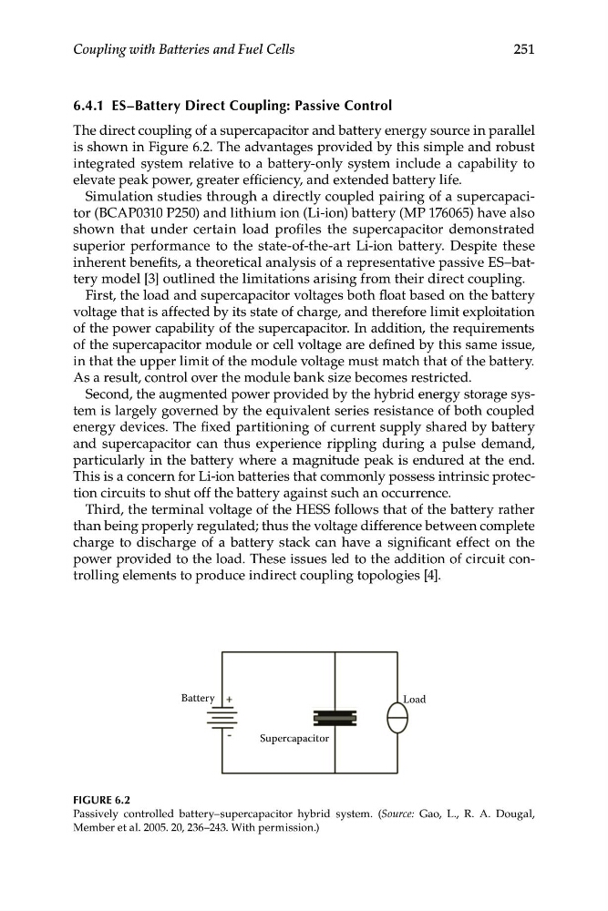
The direct coupling of a supercapacitor and battery energy source in parallel
is shown in Figure 6.2. The advantages provided by this simple and robust
integrated system relative to a battery-only system include a capability to
elevate peak power, greater efficiency, and extended battery life.
Simulation studies through a directly coupled pairing of a supercapacitor (BCAP0310 P250) and lithium ion (Li-ion) battery (MP 176065) have also
shown that under certain load profiles the supercapacitor demonstrated
superior performance to the state-of-the-art Li-ion battery. Despite these
inherent benefits, a theoretical analysis of a representative passive ES–battery model [3] outlined the limitations arising from their direct coupling.
First, the load and supercapacitor voltages both float based on the battery
voltage that is affected by its state of charge, and therefore limit exploitation
of the power capability of the supercapacitor. In addition, the requirements
of the supercapacitor module or cell voltage are defined by this same issue,
in that the upper limit of the module voltage must match that of the battery.
As a result, control over the module bank size becomes restricted.
Second, the augmented power provided by the hybrid energy storage system is largely governed by the equivalent series resistance of both coupled
energy devices. The fixed partitioning of current supply shared by battery
and supercapacitor can thus experience rippling during a pulse demand,
particularly in the battery where a magnitude peak is endured at the end.
This is a concern for Li-ion batteries that commonly possess intrinsic protection circuits to shut off the battery against such an occurrence.
Third, the terminal voltage of the HESS follows that of the battery rather
than being properly regulated; thus the voltage difference between complete
charge to discharge of a battery stack can have a significant effect on the
power provided to the load. These issues led to the addition of circuit controlling elements to produce indirect coupling topologies [4].
FIGURE 6.2
Passively controlled battery–supercapacitor hybrid system. (Source: Gao, L., R. A. Dougal,
Member et al. 2005. 20, 236–243. With permission.)
Supercapacitor
Load
251
Coupling with Batteries and Fuel Cells
6.4.1 ES–Battery Direct Coupling: Passive Control
The direct coupling of a supercapacitor and battery energy source in parallel
is shown in Figure 6.2. The advantages provided by this simple and robust
integrated system relative to a battery-only system include a capability to
elevate peak power, greater efficiency, and extended battery life.
Simulation studies through a directly coupled pairing of a supercapacitor (BCAP0310 P250) and lithium ion (Li-ion) battery (MP 176065) have also
shown that under certain load profiles the supercapacitor demonstrated
superior performance to the state-of-the-art Li-ion battery. Despite these
inherent benefits, a theoretical analysis of a representative passive ES–battery model [3] outlined the limitations arising from their direct coupling.
First, the load and supercapacitor voltages both float based on the battery
voltage that is affected by its state of charge, and therefore limit exploitation
of the power capability of the supercapacitor. In addition, the requirements
of the supercapacitor module or cell voltage are defined by this same issue,
in that the upper limit of the module voltage must match that of the battery.
As a result, control over the module bank size becomes restricted.
Second, the augmented power provided by the hybrid energy storage system is largely governed by the equivalent series resistance of both coupled
energy devices. The fixed partitioning of current supply shared by battery
and supercapacitor can thus experience rippling during a pulse demand,
particularly in the battery where a magnitude peak is endured at the end.
This is a concern for Li-ion batteries that commonly possess intrinsic protection circuits to shut off the battery against such an occurrence.
Third, the terminal voltage of the HESS follows that of the battery rather
than being properly regulated; thus the voltage difference between complete
charge to discharge of a battery stack can have a significant effect on the
power provided to the load. These issues led to the addition of circuit controlling elements to produce indirect coupling topologies [4].
FIGURE 6.2
Passively controlled battery–supercapacitor hybrid system. (Source: Gao, L., R. A. Dougal,
Member et al. 2005. 20, 236–243. With permission.)