

220
Electrochemical Supercapacitors for Energy Storage and Delivery
5.5.1 Passive Balancing
Passive balancing is classified into two subtypes: (1) resistance balancing,
and (2) Zener diode balancing.
5.5.1.1 Resistance Balancing
Resistance balancing is a simple method of maintaining control of equalized
charges across the stack. This can be done by regulating the voltage of each
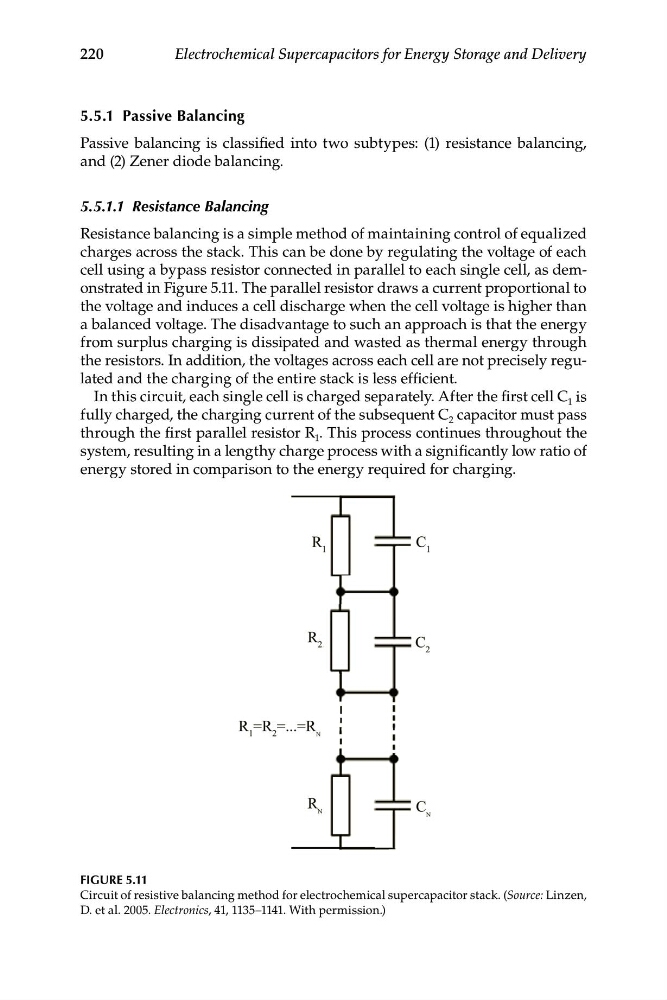
cell using a bypass resistor connected in parallel to each single cell, as demonstrated in Figure 5.11. The parallel resistor draws a current proportional to
the voltage and induces a cell discharge when the cell voltage is higher than
a balanced voltage. The disadvantage to such an approach is that the energy
from surplus charging is dissipated and wasted as thermal energy through
the resistors. In addition, the voltages across each cell are not precisely regulated and the charging of the entire stack is less efficient.
In this circuit, each single cell is charged separately. After the first cell C 1 is
fully charged, the charging current of the subsequent C 2 capacitor must pass
through the first parallel resistor R 1 . This process continues throughout the
system, resulting in a lengthy charge process with a significantly low ratio of
energy stored in comparison to the energy required for charging.
FIGURE 5.11
Circuit of resistive balancing method for electrochemical supercapacitor stack. (Source: Linzen,
D. et al. 2005. Electronics, 41, 1135–1141. With permission.)
Electrochemical Supercapacitors for Energy Storage and Delivery
5.5.1 Passive Balancing
Passive balancing is classified into two subtypes: (1) resistance balancing,
and (2) Zener diode balancing.
5.5.1.1 Resistance Balancing
Resistance balancing is a simple method of maintaining control of equalized
charges across the stack. This can be done by regulating the voltage of each
cell using a bypass resistor connected in parallel to each single cell, as demonstrated in Figure 5.11. The parallel resistor draws a current proportional to
the voltage and induces a cell discharge when the cell voltage is higher than
a balanced voltage. The disadvantage to such an approach is that the energy
from surplus charging is dissipated and wasted as thermal energy through
the resistors. In addition, the voltages across each cell are not precisely regulated and the charging of the entire stack is less efficient.
In this circuit, each single cell is charged separately. After the first cell C 1 is
fully charged, the charging current of the subsequent C 2 capacitor must pass
through the first parallel resistor R 1 . This process continues throughout the
system, resulting in a lengthy charge process with a significantly low ratio of
energy stored in comparison to the energy required for charging.
FIGURE 5.11
Circuit of resistive balancing method for electrochemical supercapacitor stack. (Source: Linzen,
D. et al. 2005. Electronics, 41, 1135–1141. With permission.)