

218
A 1
B 1 A 2
B 2
E 2
+
–
–
+
–
–
+
+
E 1
A 3
B 3
Sealants
Case
Electrochemical Supercapacitors for Energy Storage and Delivery
Titanium bipolar plate
Negative electrode material
Porous separator
Sealing rubber washer
Positive electrode material
Titanium positive end plate
Insulating rubber sheet
Stainless steel plate
(a)
(b)
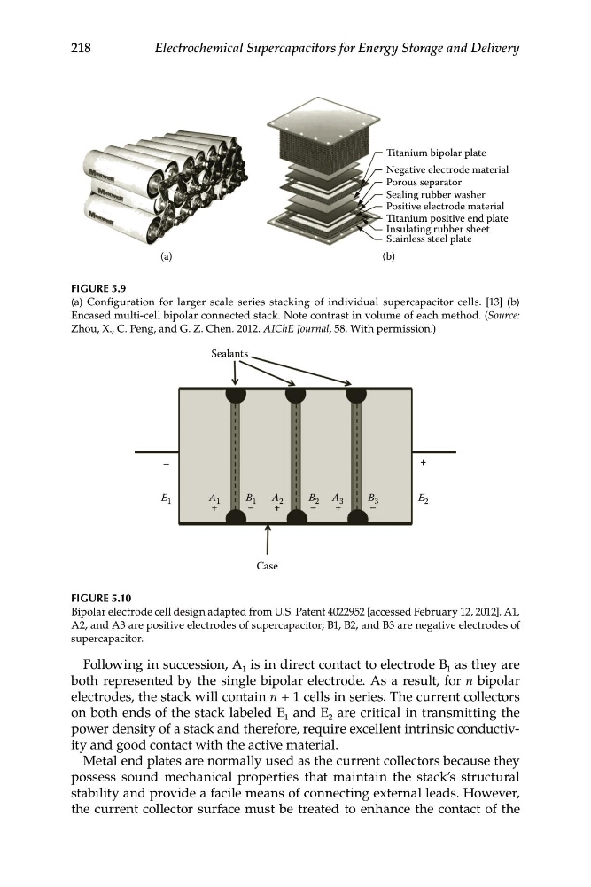
FIGURE 5.9
(a) Configuration for larger scale series stacking of individual supercapacitor cells. [13] (b)
Encased multi-cell bipolar connected stack. Note contrast in volume of each method. (Source:
Zhou, X., C. Peng, and G. Z. Chen. 2012. AIChE Journal, 58. With permission.)
FIGURE 5.10
Bipolar electrode cell design adapted from U.S. Patent 4022952 [accessed February 12, 2012]. A1,
A2, and A3 are positive electrodes of supercapacitor; B1, B2, and B3 are negative electrodes of
supercapacitor.
Following in succession, A 1 is in direct contact to electrode B 1 as they are
both represented by the single bipolar electrode. As a result, for n bipolar
electrodes, the stack will contain n + 1 cells in series. The current collectors
on both ends of the stack labeled E 1 and E 2 are critical in transmitting the
power density of a stack and therefore, require excellent intrinsic conductivity and good contact with the active material.
Metal end plates are normally used as the current collectors because they
possess sound mechanical properties that maintain the stack’s structural
stability and provide a facile means of connecting external leads. However,
the current collector surface must be treated to enhance the contact of the
A 1
B 1 A 2
B 2
E 2
+
–
–
+
–
–
+
+
E 1
A 3
B 3
Sealants
Case
Electrochemical Supercapacitors for Energy Storage and Delivery
Titanium bipolar plate
Negative electrode material
Porous separator
Sealing rubber washer
Positive electrode material
Titanium positive end plate
Insulating rubber sheet
Stainless steel plate
(a)
(b)
FIGURE 5.9
(a) Configuration for larger scale series stacking of individual supercapacitor cells. [13] (b)
Encased multi-cell bipolar connected stack. Note contrast in volume of each method. (Source:
Zhou, X., C. Peng, and G. Z. Chen. 2012. AIChE Journal, 58. With permission.)
FIGURE 5.10
Bipolar electrode cell design adapted from U.S. Patent 4022952 [accessed February 12, 2012]. A1,
A2, and A3 are positive electrodes of supercapacitor; B1, B2, and B3 are negative electrodes of
supercapacitor.
Following in succession, A 1 is in direct contact to electrode B 1 as they are
both represented by the single bipolar electrode. As a result, for n bipolar
electrodes, the stack will contain n + 1 cells in series. The current collectors
on both ends of the stack labeled E 1 and E 2 are critical in transmitting the
power density of a stack and therefore, require excellent intrinsic conductivity and good contact with the active material.
Metal end plates are normally used as the current collectors because they
possess sound mechanical properties that maintain the stack’s structural
stability and provide a facile means of connecting external leads. However,
the current collector surface must be treated to enhance the contact of the