

2
Electrochemical Supercapacitors for Energy Storage and Delivery
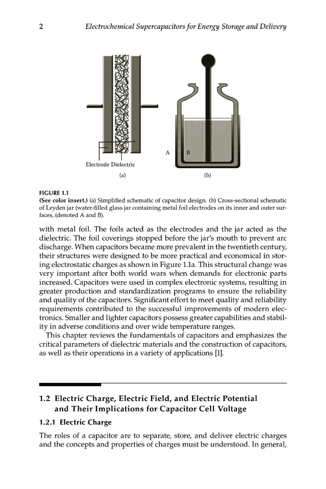
Electrode Dielectric
A
B
(a)
(b)
FIGURE 1.1
(See color insert.) (a) Simplified schematic of capacitor design. (b) Cross-sectional schematic
of Leyden jar (water-filled glass jar containing metal foil electrodes on its inner and outer surfaces, (denoted A and B).
with metal foil. The foils acted as the electrodes and the jar acted as the
dielectric. The foil coverings stopped before the jar’s mouth to prevent arc
discharge. When capacitors became more prevalent in the twentieth century,
their structures were designed to be more practical and economical in storing electrostatic charges as shown in Figure 1.1a. This structural change was
very important after both world wars when demands for electronic parts
increased. Capacitors were used in complex electronic systems, resulting in
greater production and standardization programs to ensure the reliability
and quality of the capacitors. Significant effort to meet quality and reliability
requirements contributed to the successful improvements of modern electronics. Smaller and lighter capacitors possess greater capabilities and stability in adverse conditions and over wide temperature ranges.
This chapter reviews the fundamentals of capacitors and emphasizes the
critical parameters of dielectric materials and the construction of capacitors,
as well as their operations in a variety of applications [1].
1.2 E lectric Charge, Electric Field, and Electric Potential
and Their Implications for Capacitor Cell Voltage
1.2.1 Electric Charge
The roles of a capacitor are to separate, store, and deliver electric charges
and the concepts and properties of charges must be understood. In general,