

362
M. Funahashi
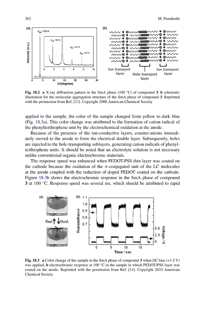
Fig. 18.2 a X-ray diffraction pattern in the SmA phase (100 °C) of compound 3, b schematic
illustration for the molecular aggregation structure of the SmA phase of compound 3. Reprinted
with the permission from Ref. [13]. Copyright 2008 American Chemical Society
applied to the sample, the color of the sample changed from yellow to dark blue
(Fig. 18.3a). This color change was attributed to the formation of cation radical of
the phenylterthiophene unit by the electrochemical oxidation at the anode.
Because of the presence of the ion-conductive layers, counter-anions immediately moved to the anode to form the electrical double layer. Subsequently, holes
are injected to the hole-transporting sublayers, generating cation radicals of phenylterthiophene units. It should be noted that an electrolyte solution is not necessary
unlike conventional organic electrochromic materials.
The response speed was enhanced when PEDOT-PSS thin layer was coated on
the cathode because the oxidation of the π-conjugated unit of the LC molecules
at the anode coupled with the reduction of doped PEDOT coated on the cathode.
Figure 18.3b shows the electrochromic response in the SmA phase of compound
3 at 100 °C. Response speed was several ms, which should be attributed to rapid
Fig. 18.3 a Color change of the sample in the SmA phase of compound 3 when DC bias (+1.5 V)
was applied, b electrochromic response at 100 °C in the sample in which PEDOT/PSS layer was
coated on the anode. Reprinted with the permission from Ref. [14]. Copyright 2010 American
Chemical Society
M. Funahashi
Fig. 18.2 a X-ray diffraction pattern in the SmA phase (100 °C) of compound 3, b schematic
illustration for the molecular aggregation structure of the SmA phase of compound 3. Reprinted
with the permission from Ref. [13]. Copyright 2008 American Chemical Society
applied to the sample, the color of the sample changed from yellow to dark blue
(Fig. 18.3a). This color change was attributed to the formation of cation radical of
the phenylterthiophene unit by the electrochemical oxidation at the anode.
Because of the presence of the ion-conductive layers, counter-anions immediately moved to the anode to form the electrical double layer. Subsequently, holes
are injected to the hole-transporting sublayers, generating cation radicals of phenylterthiophene units. It should be noted that an electrolyte solution is not necessary
unlike conventional organic electrochromic materials.
The response speed was enhanced when PEDOT-PSS thin layer was coated on
the cathode because the oxidation of the π-conjugated unit of the LC molecules
at the anode coupled with the reduction of doped PEDOT coated on the cathode.
Figure 18.3b shows the electrochromic response in the SmA phase of compound
3 at 100 °C. Response speed was several ms, which should be attributed to rapid
Fig. 18.3 a Color change of the sample in the SmA phase of compound 3 when DC bias (+1.5 V)
was applied, b electrochromic response at 100 °C in the sample in which PEDOT/PSS layer was
coated on the anode. Reprinted with the permission from Ref. [14]. Copyright 2010 American
Chemical Society