

12 Kinetic Assembly of Porous Coordination Networks …
235
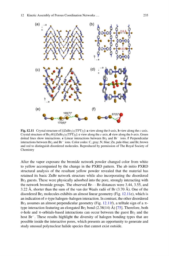
Fig. 12.11 Crystal structure of [(ZnBr 2 ) 3 (TPT) 2 ]: a view along the b-axis, b view along the c-axis.
Crystal structure of Br 2 @[(ZnBr 2 ) 3 (TPT) 2 ]: c view along the c-axis, d view along the b-axis. Green
dotted lines show interactions. e Linear interactions between Br 2 and Br − ions. f Perpendicular
interactions between Br 2 and Br − ions. Color codes: C, gray; N, blue; Zn, pale-blue; and Br, brown
and red to distinguish disordered molecules. Reproduced by permission of The Royal Society of
Chemistry
After the vapor exposure the bromide network powder changed color from white
to yellow accompanied by the change in the PXRD pattern. The ab initio PXRD
structural analysis of the resultant yellow powder revealed that the material has
retained its basic ZnBr network structure while also incorporating the disordered
Br 2 guests. These were physically adsorbed into the pore, strongly interacting with
the network bromide groups. The observed Br· · · Br distances were 3.44, 3.55, and
3.22 Å, shorter than the sum of the van der Waals radii of Br (3.70 Å). One of the
disordered Br 2 molecules exhibits an almost linear geometry (Fig. 12.11e), which is
an indication of σ-type halogen–halogen interaction. In contrast, the other disordered
Br 2 assumes an almost perpendicular geometry (Fig. 12.11f), a telltale sign of a πtype interaction featuring an elongated Br 2 bond (2.38(14) Å) [75]. Therefore, both
σ-hole and π-orbitals-based interactions can occur between the guest Br 2 and the
host Br
− . These results highlight the diversity of halogen bonding types that are
possible inside the interactive pores, which presents an opportunity to generate and
study unusual polynuclear halide species that cannot exist outside.
235
Fig. 12.11 Crystal structure of [(ZnBr 2 ) 3 (TPT) 2 ]: a view along the b-axis, b view along the c-axis.
Crystal structure of Br 2 @[(ZnBr 2 ) 3 (TPT) 2 ]: c view along the c-axis, d view along the b-axis. Green
dotted lines show interactions. e Linear interactions between Br 2 and Br − ions. f Perpendicular
interactions between Br 2 and Br − ions. Color codes: C, gray; N, blue; Zn, pale-blue; and Br, brown
and red to distinguish disordered molecules. Reproduced by permission of The Royal Society of
Chemistry
After the vapor exposure the bromide network powder changed color from white
to yellow accompanied by the change in the PXRD pattern. The ab initio PXRD
structural analysis of the resultant yellow powder revealed that the material has
retained its basic ZnBr network structure while also incorporating the disordered
Br 2 guests. These were physically adsorbed into the pore, strongly interacting with
the network bromide groups. The observed Br· · · Br distances were 3.44, 3.55, and
3.22 Å, shorter than the sum of the van der Waals radii of Br (3.70 Å). One of the
disordered Br 2 molecules exhibits an almost linear geometry (Fig. 12.11e), which is
an indication of σ-type halogen–halogen interaction. In contrast, the other disordered
Br 2 assumes an almost perpendicular geometry (Fig. 12.11f), a telltale sign of a πtype interaction featuring an elongated Br 2 bond (2.38(14) Å) [75]. Therefore, both
σ-hole and π-orbitals-based interactions can occur between the guest Br 2 and the
host Br
− . These results highlight the diversity of halogen bonding types that are
possible inside the interactive pores, which presents an opportunity to generate and
study unusual polynuclear halide species that cannot exist outside.