

4
K. D. M. Harris et al.
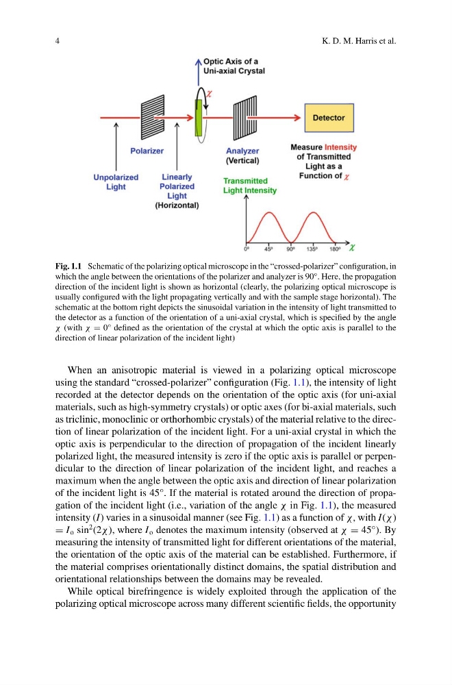
Fig. 1.1 Schematic of the polarizing optical microscope in the “crossed-polarizer” configuration, in
which the angle between the orientations of the polarizer and analyzer is 90°. Here, the propagation
direction of the incident light is shown as horizontal (clearly, the polarizing optical microscope is
usually configured with the light propagating vertically and with the sample stage horizontal). The
schematic at the bottom right depicts the sinusoidal variation in the intensity of light transmitted to
the detector as a function of the orientation of a uni-axial crystal, which is specified by the angle
χ (with χ = 0° defined as the orientation of the crystal at which the optic axis is parallel to the
direction of linear polarization of the incident light)
When an anisotropic material is viewed in a polarizing optical microscope
using the standard “crossed-polarizer” configuration (Fig. 1.1), the intensity of light
recorded at the detector depends on the orientation of the optic axis (for uni-axial
materials, such as high-symmetry crystals) or optic axes (for bi-axial materials, such
as triclinic, monoclinic or orthorhombic crystals) of the material relative to the direction of linear polarization of the incident light. For a uni-axial crystal in which the
optic axis is perpendicular to the direction of propagation of the incident linearly
polarized light, the measured intensity is zero if the optic axis is parallel or perpendicular to the direction of linear polarization of the incident light, and reaches a
maximum when the angle between the optic axis and direction of linear polarization
of the incident light is 45°. If the material is rotated around the direction of propagation of the incident light (i.e., variation of the angle χ in Fig. 1.1), the measured
intensity (I) varies in a sinusoidal manner (see Fig. 1.1) as a function of χ, with I(χ )
= I o sin
2 (2χ ), where I o denotes the maximum intensity (observed at χ = 45°). By
measuring the intensity of transmitted light for different orientations of the material,
the orientation of the optic axis of the material can be established. Furthermore, if
the material comprises orientationally distinct domains, the spatial distribution and
orientational relationships between the domains may be revealed.
While optical birefringence is widely exploited through the application of the
polarizing optical microscope across many different scientific fields, the opportunity
K. D. M. Harris et al.
Fig. 1.1 Schematic of the polarizing optical microscope in the “crossed-polarizer” configuration, in
which the angle between the orientations of the polarizer and analyzer is 90°. Here, the propagation
direction of the incident light is shown as horizontal (clearly, the polarizing optical microscope is
usually configured with the light propagating vertically and with the sample stage horizontal). The
schematic at the bottom right depicts the sinusoidal variation in the intensity of light transmitted to
the detector as a function of the orientation of a uni-axial crystal, which is specified by the angle
χ (with χ = 0° defined as the orientation of the crystal at which the optic axis is parallel to the
direction of linear polarization of the incident light)
When an anisotropic material is viewed in a polarizing optical microscope
using the standard “crossed-polarizer” configuration (Fig. 1.1), the intensity of light
recorded at the detector depends on the orientation of the optic axis (for uni-axial
materials, such as high-symmetry crystals) or optic axes (for bi-axial materials, such
as triclinic, monoclinic or orthorhombic crystals) of the material relative to the direction of linear polarization of the incident light. For a uni-axial crystal in which the
optic axis is perpendicular to the direction of propagation of the incident linearly
polarized light, the measured intensity is zero if the optic axis is parallel or perpendicular to the direction of linear polarization of the incident light, and reaches a
maximum when the angle between the optic axis and direction of linear polarization
of the incident light is 45°. If the material is rotated around the direction of propagation of the incident light (i.e., variation of the angle χ in Fig. 1.1), the measured
intensity (I) varies in a sinusoidal manner (see Fig. 1.1) as a function of χ, with I(χ )
= I o sin
2 (2χ ), where I o denotes the maximum intensity (observed at χ = 45°). By
measuring the intensity of transmitted light for different orientations of the material,
the orientation of the optic axis of the material can be established. Furthermore, if
the material comprises orientationally distinct domains, the spatial distribution and
orientational relationships between the domains may be revealed.
While optical birefringence is widely exploited through the application of the
polarizing optical microscope across many different scientific fields, the opportunity